Optical disk device

a technology of optical disk and optical beam, which is applied in the field of optical disk devices, can solve the problems of increasing cost, increasing error rate and jitter after recording, and insufficient servo tracking performan

Inactive Publication Date: 2003-05-08
TEAC CORP
View PDF4 Cites 59 Cited by
  • Summary
  • Abstract
  • Description
  • Claims
  • Application Information

AI Technical Summary

Problems solved by technology

Accordingly, when optimum recording power cannot be obtained for each optical disk, an error rate and jitter after recording can greatly increas.
However, in the case where high speed recording is performed, when the rotational speed of the optical disk is raised, a spindle motor that has high torque is required, resulting in cost increase.
Furthermore, in this case, since vibration is generated at the time of the high speed rotation, servo tracking performance becomes ina

Method used


Image

  • Optical disk device
  • Optical disk device
  • Optical disk device

Examples


Embodiment Construction

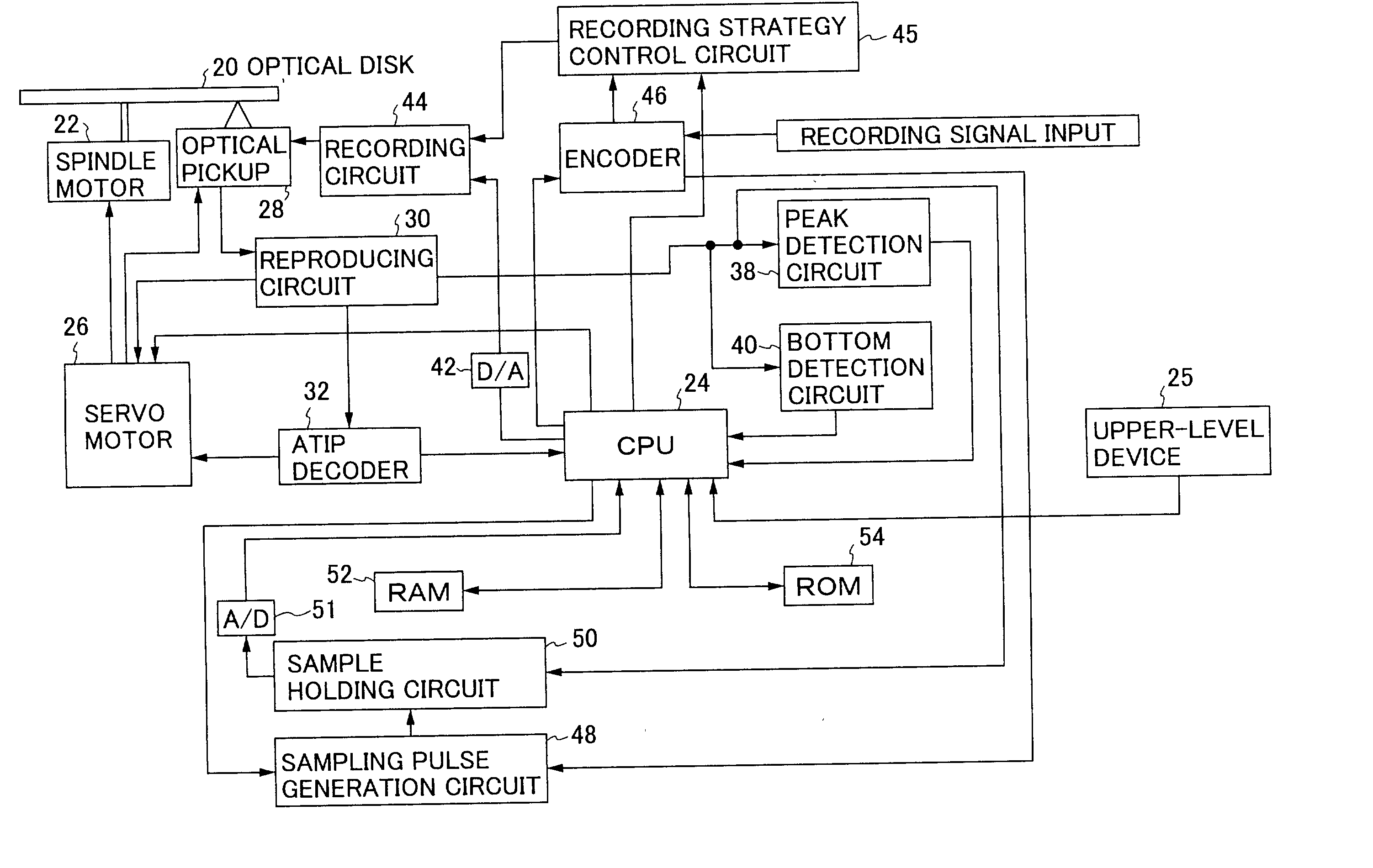
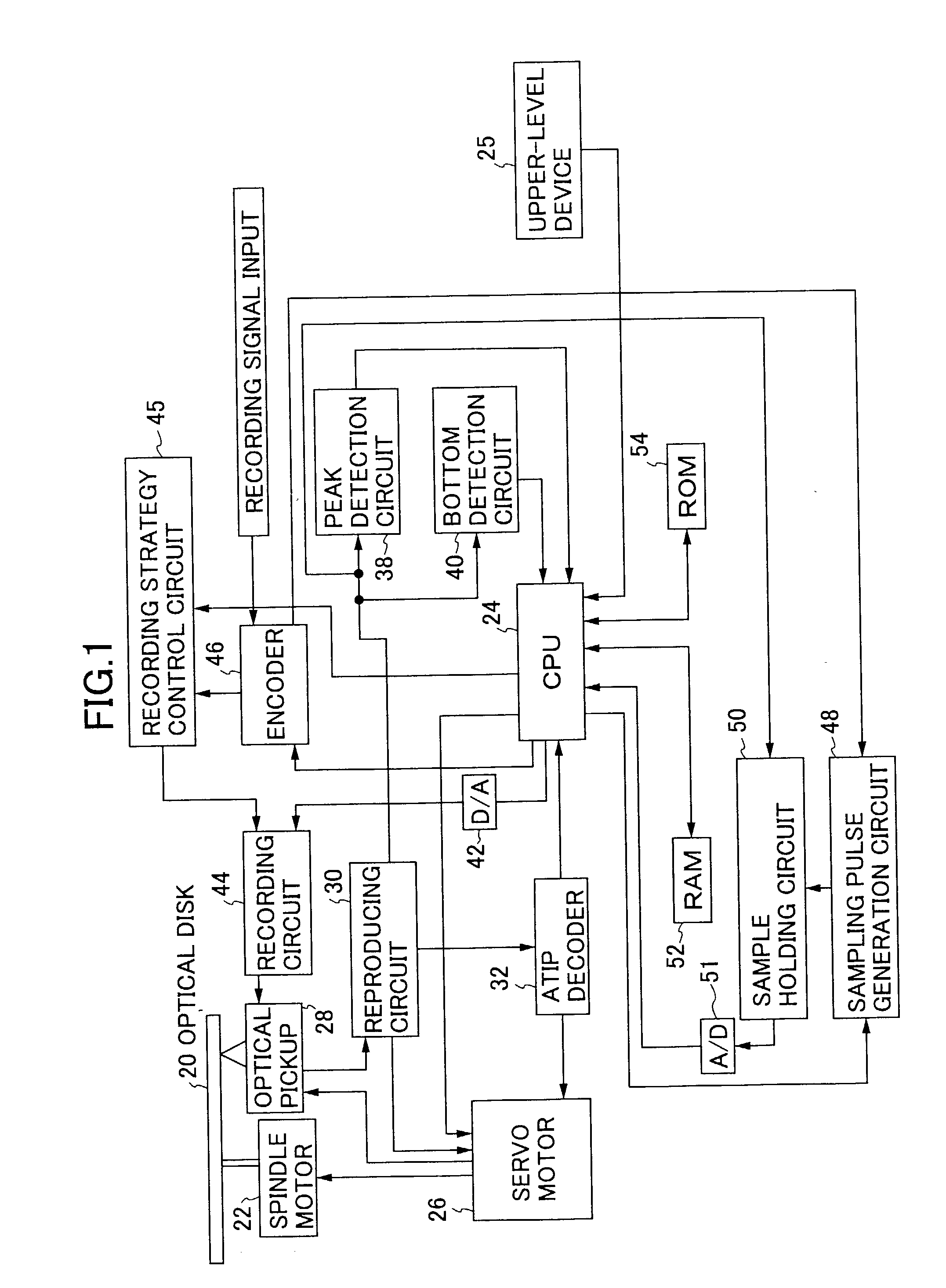
[0026] FIG. 1 is a block diagram showing one embodiment of an optical disk device according to the present invention. In FIG. 1, an optical disk 20 is driven and rotated by a spindle motor 22. A CPU 24 provides a command to a servo circuit 26 in accordance with a writing / reading command given by an upper-level device 25.

[0027] The servo circuit 26 controls a rotational speed of the spindle motor 22 based on a recording speed provided by the CPU, and may perform CLV servo. Furthermore, the servo circuit 26 performs rotational control of a thread motor of an optical pickup 28 to move the optical pickup 28 to a desired block of the optical disk, and performs focus servo and tracking servo of the optical pickup 28.

[0028] Laser light emitted from the optical pickup 28 is reflected on a recording surface of the optical disk 20, and the reflected beam is then detected by the optical pickup 28. A reproducing RF signal obtained in the optical pickup is provided to a reproducing circuit 30. A...


PUM


Abstract

An optical disk device for estimating optimum recording power for high speed recording at an outer part of an optical disk, with high accuracy, even when an OPC for high speed recording at the outer part cannot be performed. The optical disk device includes a first optimum recording power calculation part for performing test recording at a first speed lower than the maximum recording speed of a test area by using recording parameters of a required recording speed to calculate first optimum recording power, and a second optimum recording power calculation part for performing test recording at a second speed to calculate second optimum recording power. The first speed is different from the second speed. The optical disk device further includes an estimation part for estimating optimum recording power for based on the first optimum recording power and the second optimum recording power.

Description

[0001] 1. Field of the Invention[0002] The present invention relates to an optical disk device, and specifically to an optical disk device that performs recording on a write-once optical disk.[0003] 2. Description of the Related Art[0004] There are two types of recording optical disks. That is, there are a write-once type and an erasable type. As for the write-once type, Te and Bi are used as material for a signal recording surface of the write-once optical disk, and the signal recording surface is irradiated by laser light to melt the surface and form a pit. Alternatively, a thin film of Sb.sub.2Se.sub.3, TeOx or an organic pigment is used as materials for the recording surface, and the recording surface is irradiated by laser light to vary light reflectance.[0005] A CD-R which is the write-once type is provided with a pre-groove used as a guide. The pre-groove has a center frequency of 22.05 kHz, and slightly wobbles in a radial direction. Address information used at the time of r...

Claims


Application Information

Patent Timeline
IPC IPC(8): G11B7/0045G11B7/125G11B7/126
CPCG11B7/126G11B7/0045
Inventor FUKUMOTO, MAKOTO
Owner TEAC CORP
Why Eureka
Try Eureka