
Flat illuminator with flexible integral switching arm

a technology of flat illuminators and switching arms, which is applied in the direction of semiconductor devices for light sources, light and heating apparatus, keys, etc., can solve the problem of not fitting in the credit card slo

Inactive Publication Date: 2003-06-12
KRIETZMAN MARK HOWARD +1
View PDF9 Cites 39 Cited by
  • Summary
  • Abstract
  • Description
  • Claims
  • Application Information

AI Technical Summary

Problems solved by technology

The Sinclair flashlight uses is the size of a deck of playing card and will not fit in the credit card slot of a wallet.

Method used


Image

  • Flat illuminator with flexible integral switching arm
  • Flat illuminator with flexible integral switching arm
  • Flat illuminator with flexible integral switching arm

Examples


Embodiment Construction

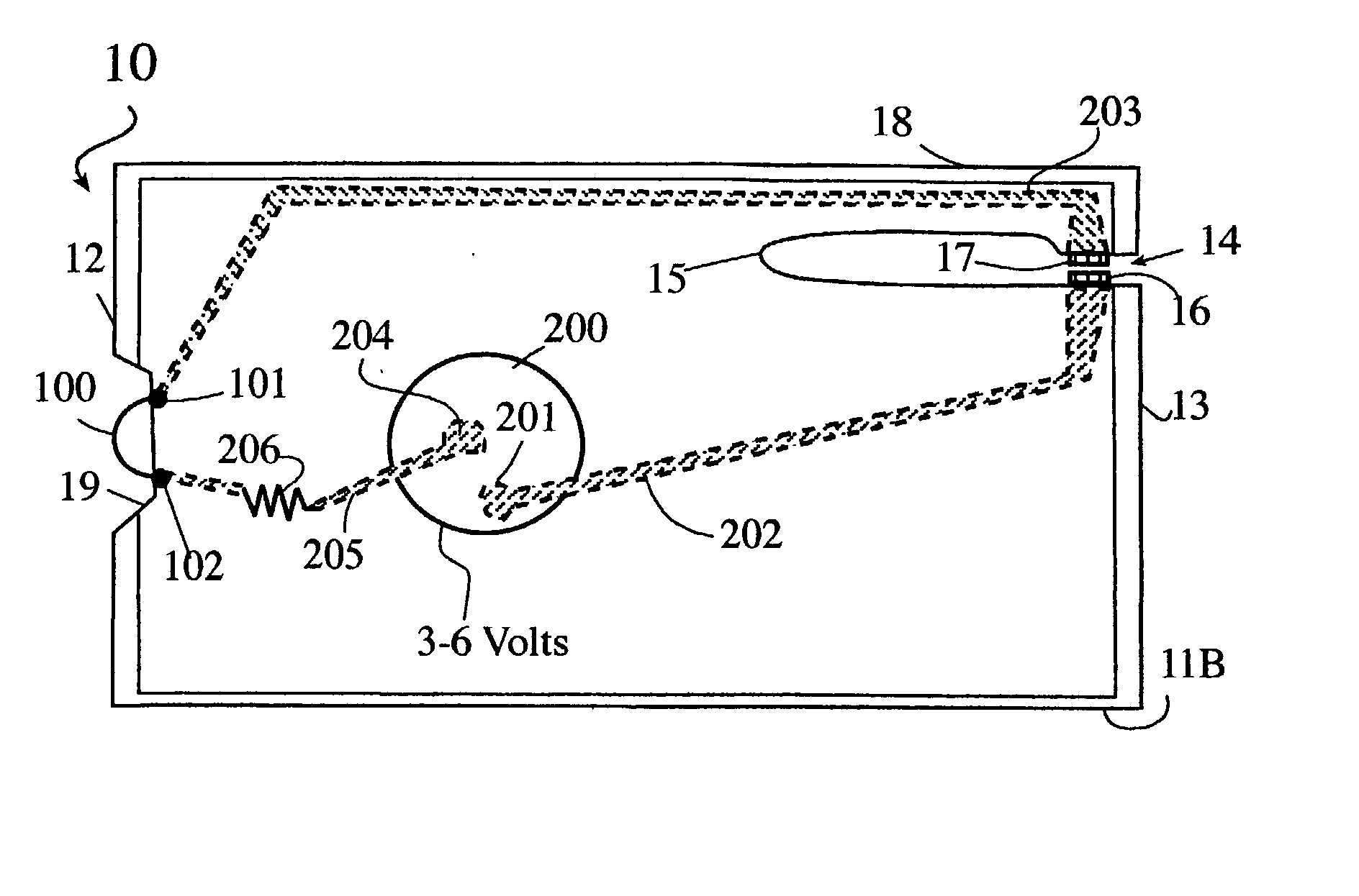
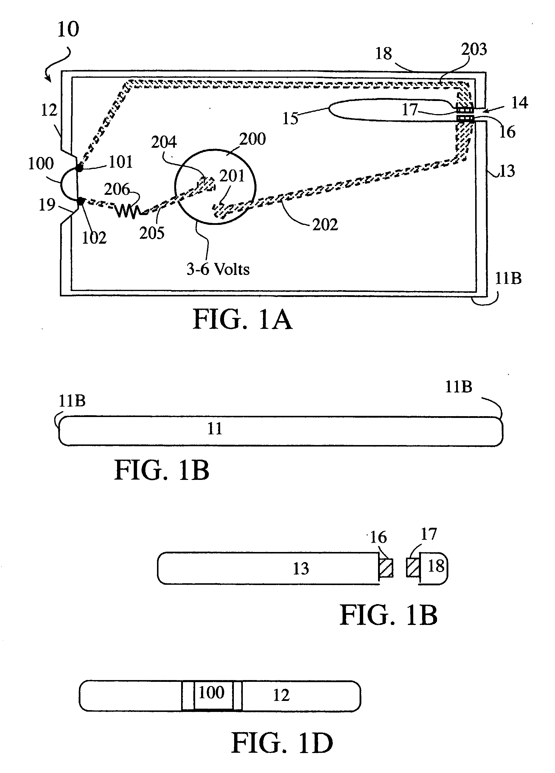
[0029] Illustrated in FIGS. 1A,1B, 1C and 1D, are top, front, rear and side views of the preferred embodiment of the flat card light generally designated 10 and constructed on a planar plastic body 11A with an edge thickness between about 1.0 mm and about 3.5 mm, tapered or beveled around some or all of the periphery 11B and shaped to fit within the credit card slot of a wallet and has a front edge 12 and a back edge 13. Formed integrally in the back edge 13 is a horizontal pressure switch 14.

[0030] The horizontal pressure switch 14 lays flat and does not exceed the thickness of the plastic body 11A. A switch guide 15 is formed, or die-cut, in a portion of the plastic body 11A and the periphery 11B, forming a flexible switching arm 18, of the horizontal pressure switch 14, which extends from the plastic body 11A. A first switch contact 16 is affixed to the flexible switching arm 18 and a second switch contact 17 is affixed on opposite side of the switch guide 15. The flexible switch...


PUM


Abstract

A flat illuminator with a flexible switching arm that connects a battery power supply to an LED illumination source. Multi-layered construction combined with conductive inks, wires or foils are used to link the battery and LED illumination source while maintaining a thin credit card-like profile.

Description

1. RELATED APPLICATIONS[0001] The invention is a continuation-in-part of Applicants application Ser. No. 09 / 740,472 entitled FLAT CREDIT CARD ILLUMINATOR WITH FLEXIBLE INTEGRAL SWITCHING ARM now U.S. Pat. No. ______ which claimed the benefit of Provisional Application Nos. 60 / 172,985, 60 / 202,894, and 60 / 253,188. And which now claims the benefit, under Title 35, United States Code 119 (e), of Provisional Application No. 60 / 330,366, filed Oct. 22, 2001, entitled MULTI-LAYERED FLAT ILLUMINATOR all of which are hereby incorporated by this reference.[0002] 1. Field of the Invention[0003] This present invention relates to a thin flat illuminator. More particularly to a plastic card-like light which illuminates with one or more light-emitting diodes "LEDs" and is switched on / off with a flexible switching arm.[0004] 2. Related Arts[0005] A recent card light found in U.S. Pat. No. 6,070,990 assigned to the Eveready Battery Company illustrates how a single button battery may be sandwiched bet...

Claims


Application Information

Patent Timeline
IPC IPC(8): E05B17/10E05B19/26F21L4/00F21L4/02F21V23/04
CPCE05B17/103E05B19/26F21Y2101/02F21L4/027F21V23/0414F21L4/005F21Y2115/10
Inventor KRIETZMAN, MARK HOWARDCHEN, YU-HSIN
Owner KRIETZMAN MARK HOWARD
Features
  • Generate Ideas
  • Intellectual Property
  • Life Sciences
  • Materials
  • Tech Scout
  • Unparalleled Data Quality
  • Higher Quality Content
  • 60% Fewer Hallucinations
Learn More