Vehicle information recording system
- Summary
- Abstract
- Description
- Claims
- Application Information
AI Technical Summary
Benefits of technology
Problems solved by technology
Method used
Image

Examples
first embodiment
[0050] (The First Embodiment)
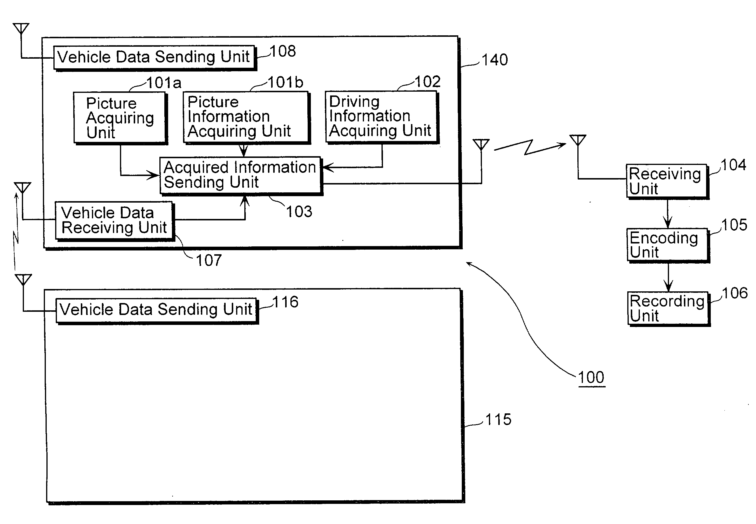
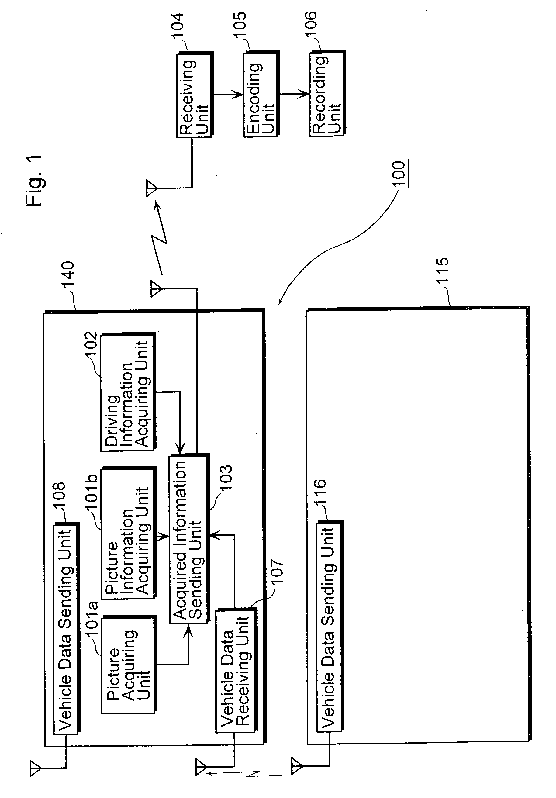
[0051] The first embodiment of the present invention will be explained with reference to the figures. FIG. 1 is a block diagram showing an overall structure of the vehicle information recording system according to the first embodiment of the present invention.
[0052] The vehicle information recording system 100 includes (i) an in-vehicle information acquiring unit 140 which is mounted in a vehicle such as a car, including a picture acquiring unit 101a, a picture information acquiring unit 101b, a driving information acquiring unit 102, a vehicle data receiving unit 107, a vehicle data sending unit 108 and an acquired information sending unit 103, (ii) an in-vehicle information acquiring unit 115 which is mounted in another vehicle, including a vehicle data sending unit 116, (iii) a receiving unit 104, an encoding unit 105 and (v) a recording unit 106, which are respectively placed outside the vehicles.
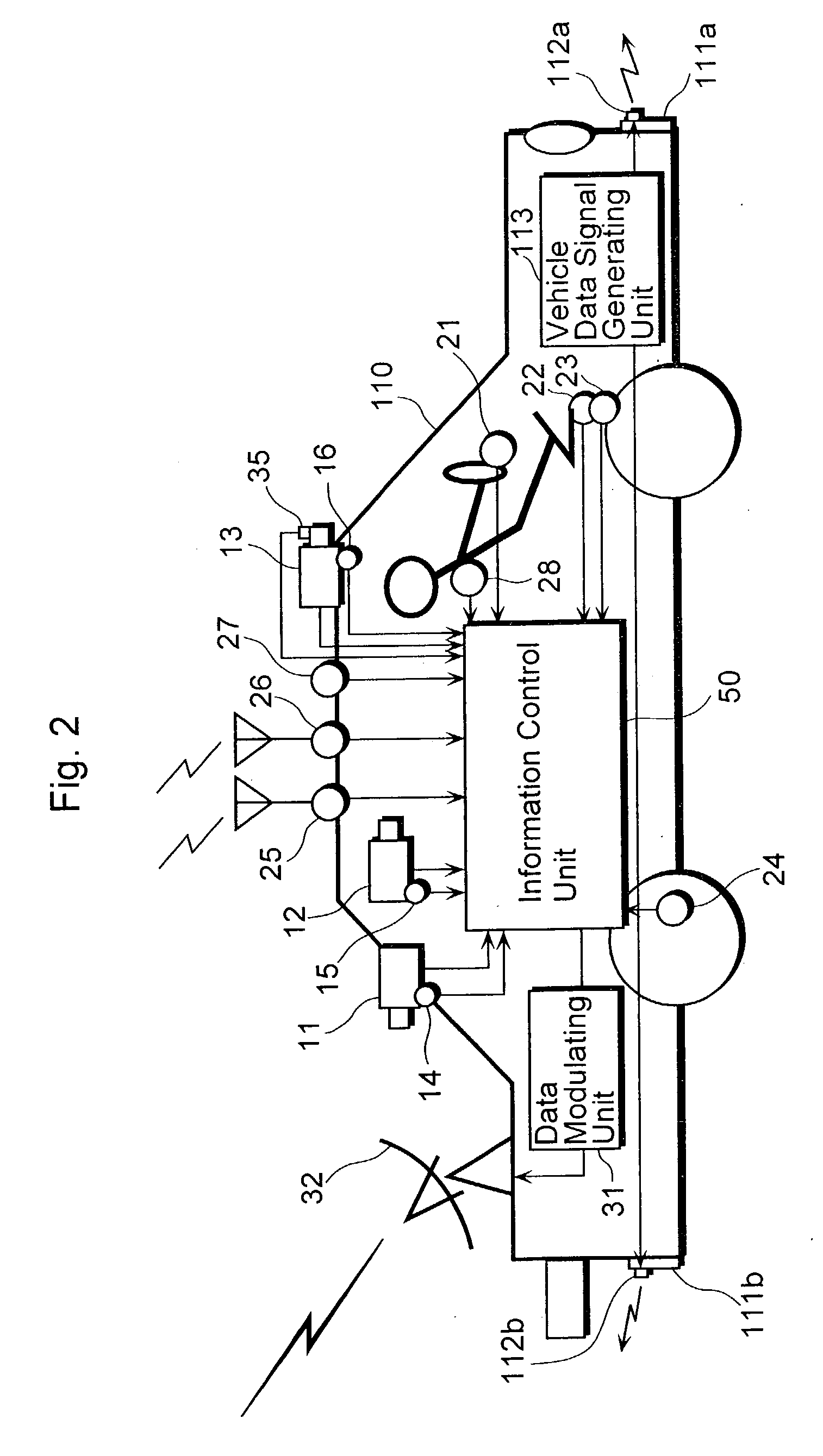
[0053] FIG. 2 is a diagram showing how respective unit...
case 1
[0086] (Case 1)
[0087] FIG. 6 is a diagram showing a running condition on the road of the vehicles equipped with the vehicle information recording system. FIG. 6 shows the running condition of the vehicle 110. In the front of the vehicle 110, the vehicle 120 is running, and further in front of them, the vehicle 130 is coming from the opposite direction.
[0088] FIG. 7 is a flowchart showing schematic operation in the vehicle information recording system 100.
[0089] First, the picture acquiring unit 101a, the picture information acquiring unit 101b, the driving information acquiring unit 102, and the vehicle data receiving unit 107 which are mounted on the vehicle 110 acquire data such as picture data, picture-related information, driving-related information and other vehicle data (Step S101).
[0090] More specifically, the cameras 11, 12 and 13 mounted on the vehicle 110 acquire pictures of the rear view, front view and inside of the vehicle 110 taken at fixed intervals on an intermittent...
case 2
[0159] (Case 2)
[0160] FIG. 10 is a diagram showing a running condition on the road of the vehicles equipped with the vehicle information recording system. FIG. 10 shows the running condition on the road of the vehicle 110. FIG. 10 is different from FIG. 6 in that the vehicles 120 and 130 are equipped with the in-vehicle information acquiring unit 140 shown in FIG. 1 just like the vehicle 110. Since the other points are same, the explanation thereof will be omitted.
[0161] As for the vehicle 110, the integrated driving information file 401 is stored in the recording unit 106, as described above.
[0162] Also, s for the vehicle 120, the integrated driving information file 401 is stored in the recording unit 106.
[0163] FIG. 11 is a data diagram showing the integrated driving information file concerning the picture data taken by the camera 125 which is mounted on the vehicle 120 to take forward pictures.
[0164] The integrated driving information file 701 has a format in which the header sec...
PUM
 Abstract
Description
Claims
Application Information
 - Generate Ideas
- Intellectual Property
- Life Sciences
- Materials
- Tech Scout
- Unparalleled Data Quality
- Higher Quality Content
- 60% Fewer Hallucinations
Browse by: Latest US Patents, China's latest patents, Technical Efficacy Thesaurus, Application Domain, Technology Topic, Popular Technical Reports.
© 2025 PatSnap. All rights reserved.Legal|Privacy policy|Modern Slavery Act Transparency Statement|Sitemap|About US| Contact US: help@patsnap.com