Bottle containment cap

a technology for containment caps and bottles, applied in the direction of liquid handling, application, closures using stoppers, etc., can solve the problems of cap allowing gas to escape, carbonated beverages lose their effervescence after, and pumps systems, etc., to prevent the release of gas

Inactive Publication Date: 2003-07-31
SEKENDUR ORAL FATIH
View PDF0 Cites 27 Cited by
  • Summary
  • Abstract
  • Description
  • Claims
  • Application Information

AI Technical Summary

Benefits of technology

0006] It is an object of the present invention to maintain the effervescence of bottled carbonated beverages.
0007] It is an object of the present invention to prevent the release of gas from bottled carbonated beverages.
0008] It is an object of the present invention to dispense only liquid from bottled carbonated beverages.
0009] It is an object of the present invention to prevent gas from escaping from bottled carbonated beverages yet at the same time allows the liquid carbonated beverage to be dispensed.
0010] It is an object of the present invention to allow normal pouring of a liquid carbonated beverage by removing the containment cap in the present invention entirely from the bottle and purring the beverage in the normal manner.
0011] It is an object of the present invention to overcome the disadvantages of previous methods of maintaining the effervescence in liquid carbonated beverages.

Problems solved by technology

It is well known that carbonated beverages lose their effervescence after the bottle is opened.
The disadvantage of the resealable cap systems is that the cap allows gas to escape each time the cap is opened and the bottle is depressurized.
The pumps systems also have disadvantages including those already mentioned for the resealable cap.
The pump attempts to repressurize the bottle, but is unable to replace the effervescence in the beverage.
Additionally, repressurizing the bottle with the pump is time consuming and inconvenient.

Method used


Image

  • Bottle containment cap
  • Bottle containment cap
  • Bottle containment cap

Examples


first embodiment

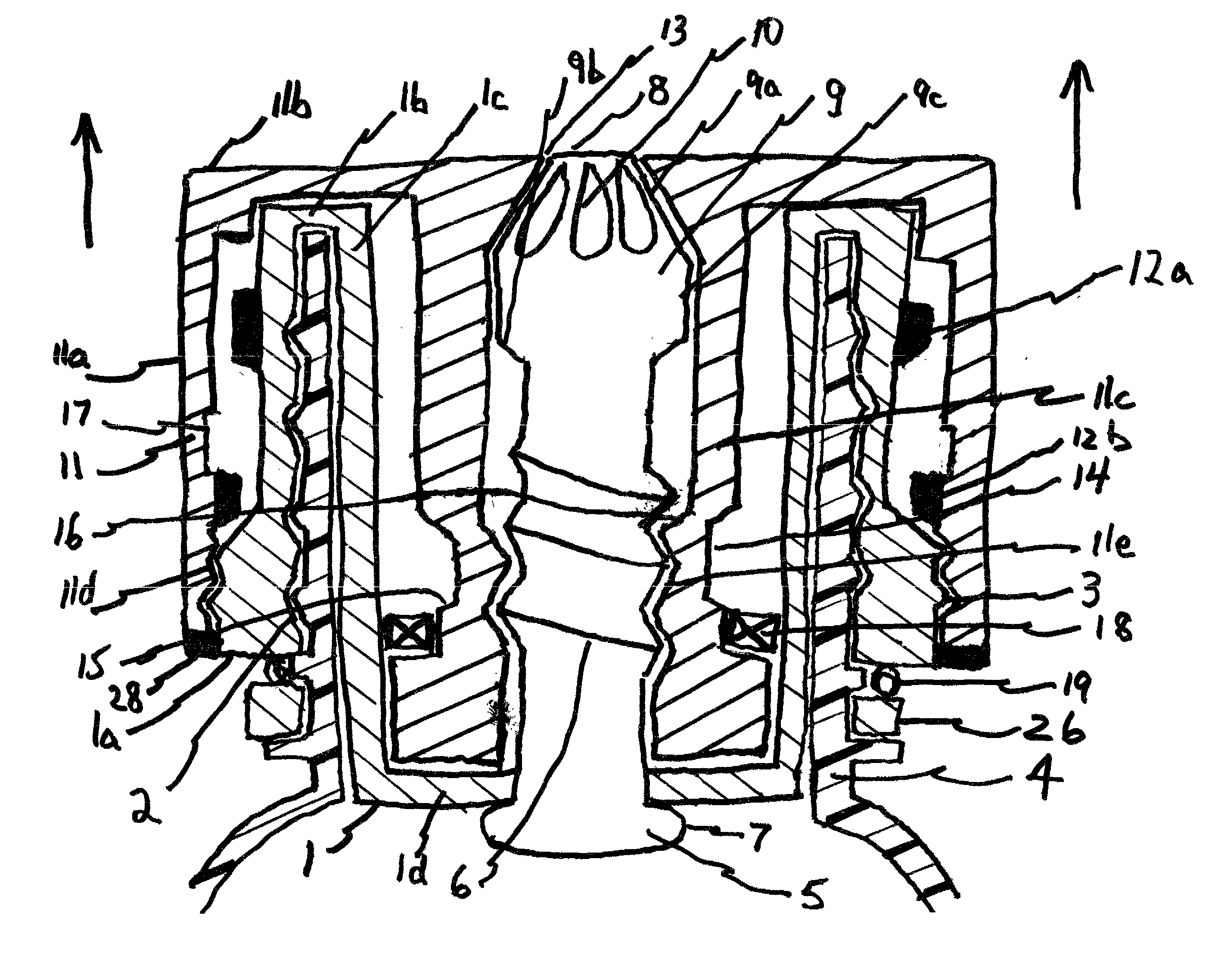
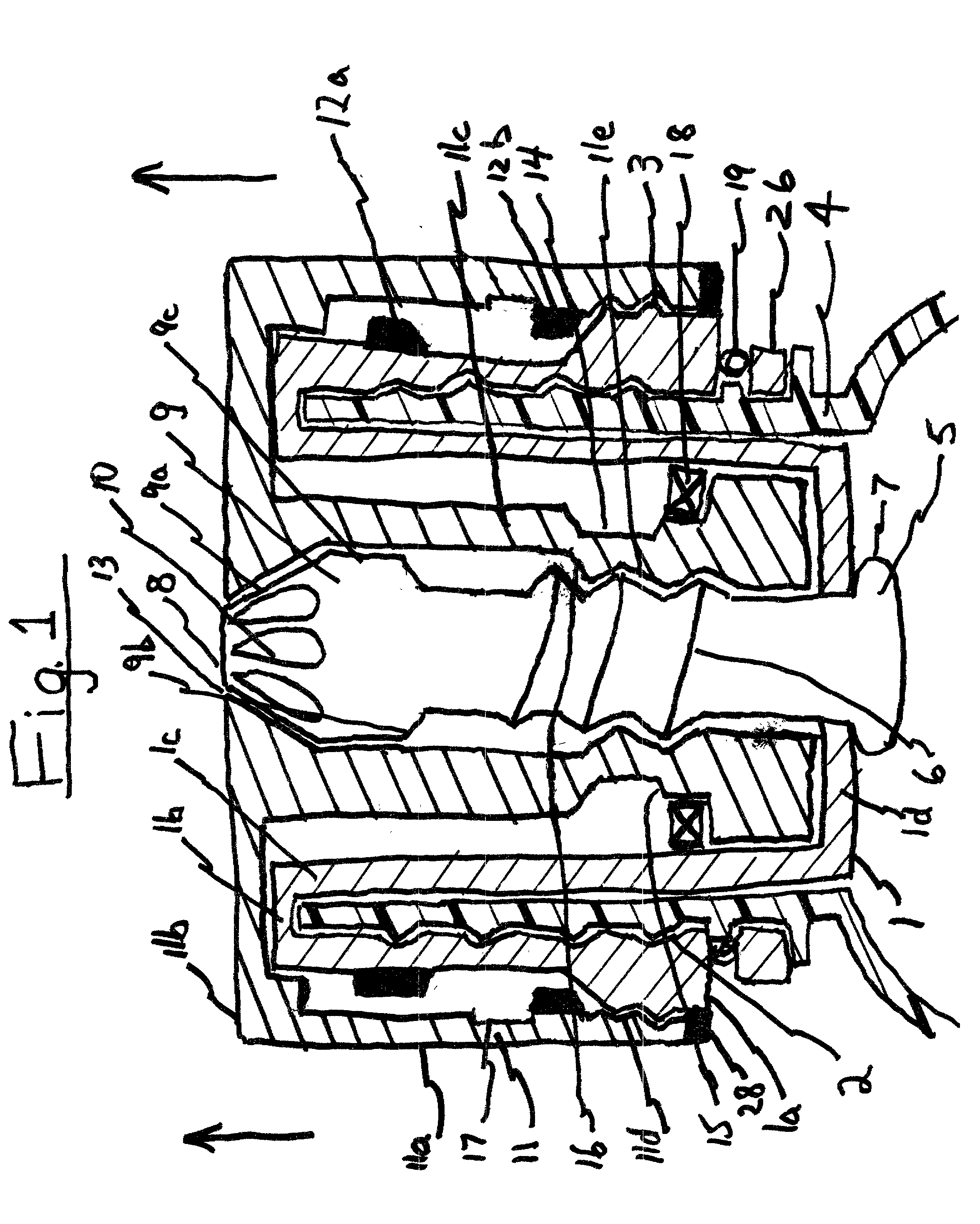
[0022] In a first embodiment, the containment cap in the present invention has an inner valve assembly 1 in FIG. 1. comprising an outer side 1a, a top side 1b, an inner side 1c and a bottom side 1d. The outer side comprises an inner thread 2 designed to screw on a bottle neck 4 and outer thread 3 designed to screw on an outer valve assembly 11. The inner side 1c fits against the inside wall of the bottle neck.

[0023] The bottom side of the inner valve assembly comprises a tubular valve assembly 5. Details of the tubular valve assembly are not described since the art is already known. The tubular valve assembly has a threaded tubular body member 6, a base end 7, a top end 8, a tapered head member 9 and a tapered opening 10. The tapered head has a top tapered end 9a, a bottom tapered end 9b and a side end 9c.

[0024] Further, the inner valve assembly comprises an inner stop 12a that will engage an outer stop 12b on the outer valve assembly when the outer valve assembly is unscrewed to a ...

third embodiment

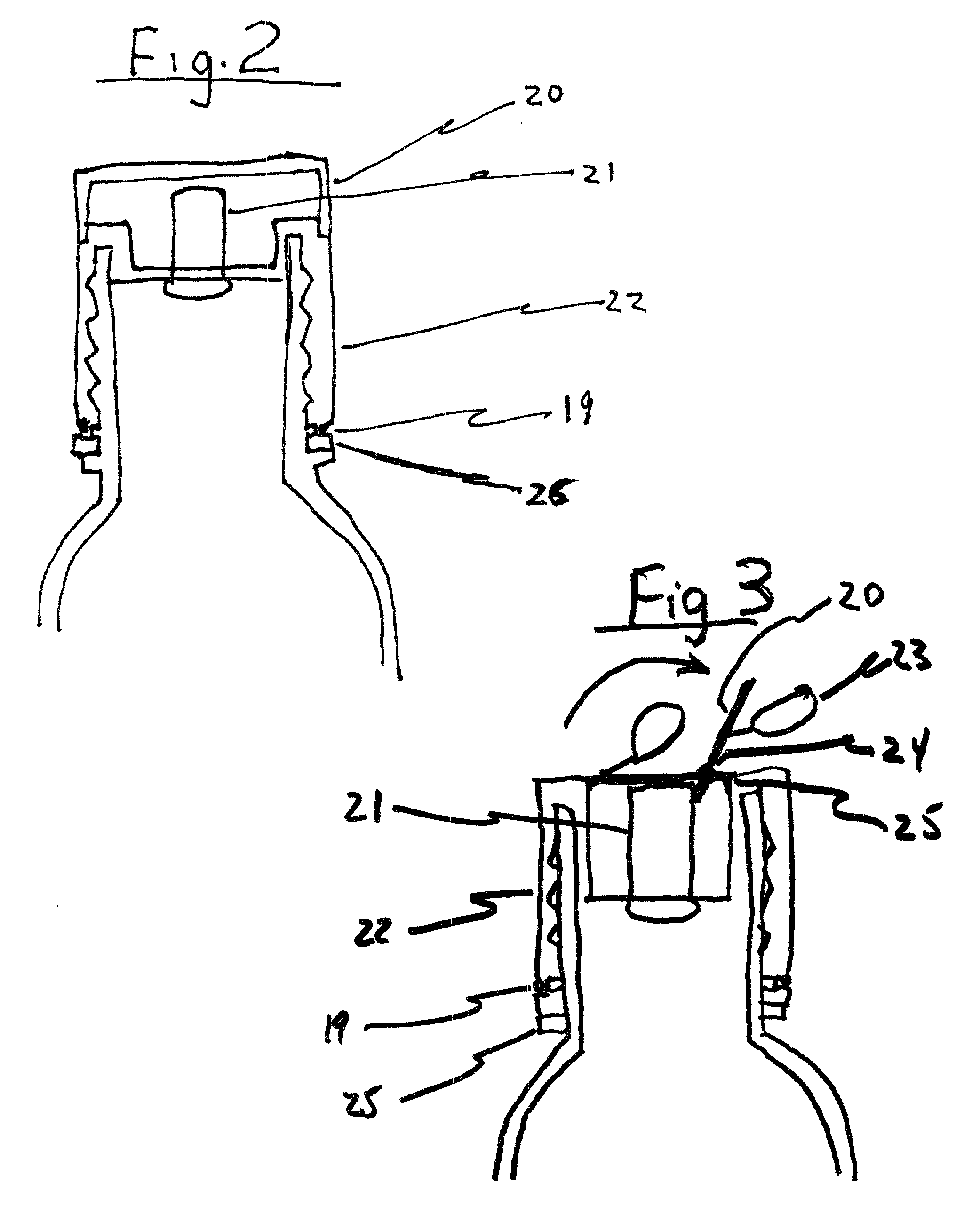
[0033] In a third embodiment in FIG. 3, the containment cap comprises the cap assembly 22 that recesses the valve assembly 21 inside the bottle neck. The containment cap is opened by pulling on a tab 23 to release the protective cap 20. The protective cap is secured off-center on the cap assembly by a hinge 24. The hinge allows the protective cap to rotate upward and act as a lever. When pulled, the lower end of the protective cap engages laterally the upper end of the valve assembly to force it open to expel the carbonated liquid when the bottle is in the upside down pouring position. The protective cap can be resealed by pushing and snapping it back to its original closed position using a snapping means 25 for snapping the protective cap in the closed position.

fourth embodiment

[0034] In fourth embodiment, the containment cap in the present invention has an inner valve assembly 1 in FIG. 4. comprising an outer side 1a and a top side 1b designed to fit on a bottle neck. The outer side has outer staggered threads 29 designed to screw on the inner staggered threads 30 of an outer valve assembly 11.

[0035] The top side of the inner valve assembly comprises a valve assembly 21. The valve assembly has angled spokes 27 arranged in a circular pattern radiating from the center of the inner valve assembly, safety seal 28, inner staggered threads 29, stop recess 31, perforation 19 and lock ring 26. The safety seal is broken the first time the outer valve assembly is opened.

[0036] The outer valve assembly 11 fits over the inner valve assembly. It comprises an outer wall 11a having inner staggered threads 30, a top wall 11b having spoke holes 32 arranged in a circular pattern radiating from the center to fit the angled spokes of the inner valve assembly and a outer stop...


PUM


Abstract

This invention relates to the containment of effervescence in carbonated beverages through the use of a containment cap designed to expel only carbonated liquid and contain the gas within the bottle. The present invention uses an aerosol valve assembly similar to those used to dispense whipped cream from cans.

Description

DESCRIPTION OF PRIOR ART[0001] The following United States Patents are most closely related to the present invention:1 U.S. Patent Documents 4,515,019 4,723,670 4,763,802 5,031,785 5,207,339 5,294,010 5,322,094 6,113,070[0002] It is well known that carbonated beverages lose their effervescence after the bottle is opened. There have been many attempts to reduce lose of gas by the use of various kinds of resealable bottle tops and the use of pumps to repressurize the bottle.[0003] The disadvantage of the resealable cap systems is that the cap allows gas to escape each time the cap is opened and the bottle is depressurized. After several openings, the beverage loses carbonation.[0004] The pumps systems also have disadvantages including those already mentioned for the resealable cap. Each time the bottle is opened, pressure is released. The pump attempts to repressurize the bottle, but is unable to replace the effervescence in the beverage. Depressurization releases effervescence that i...

Claims


Application Information

Patent Timeline
Patent Type & Authority Applications(United States)
IPC IPC(8): B65D47/24
CPCB65D47/246B65D47/242
Inventor SEKENDUR, ORAL FATIH
Owner SEKENDUR ORAL FATIH
Why Eureka
Try Eureka