Modulated optical mouse for a personal computer

a moduled, optical mouse technology, applied in the field of optical mouse, can solve the problems of high cost, limited movement of computer mouse, and malfunction of tracking moduler,

Inactive Publication Date: 2003-07-31
UNITY OPTO TECH CO LTD
View PDF4 Cites 28 Cited by
  • Summary
  • Abstract
  • Description
  • Claims
  • Application Information

AI Technical Summary

Problems solved by technology

Therefore, the movement of the computer mouse is limited by the length of the wire and also the space available on the reflection surface.
Furthermore, due to a long period of time rolling on the reflection surface, the tracking ball is easily contaminated by the dust on the

Method used


Image

  • Modulated optical mouse for a personal computer
  • Modulated optical mouse for a personal computer
  • Modulated optical mouse for a personal computer

Examples


Embodiment Construction

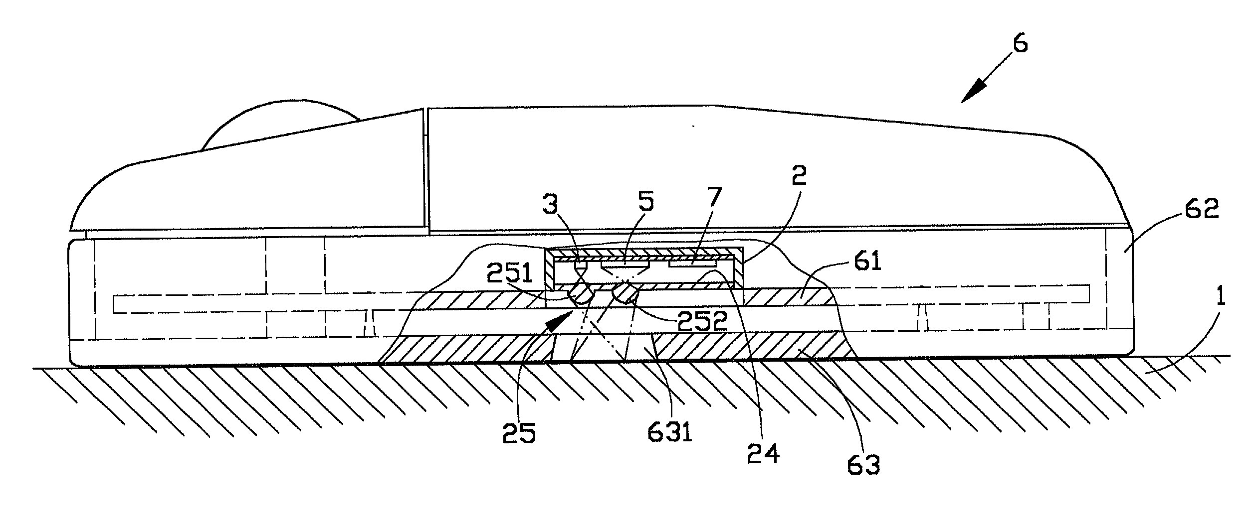
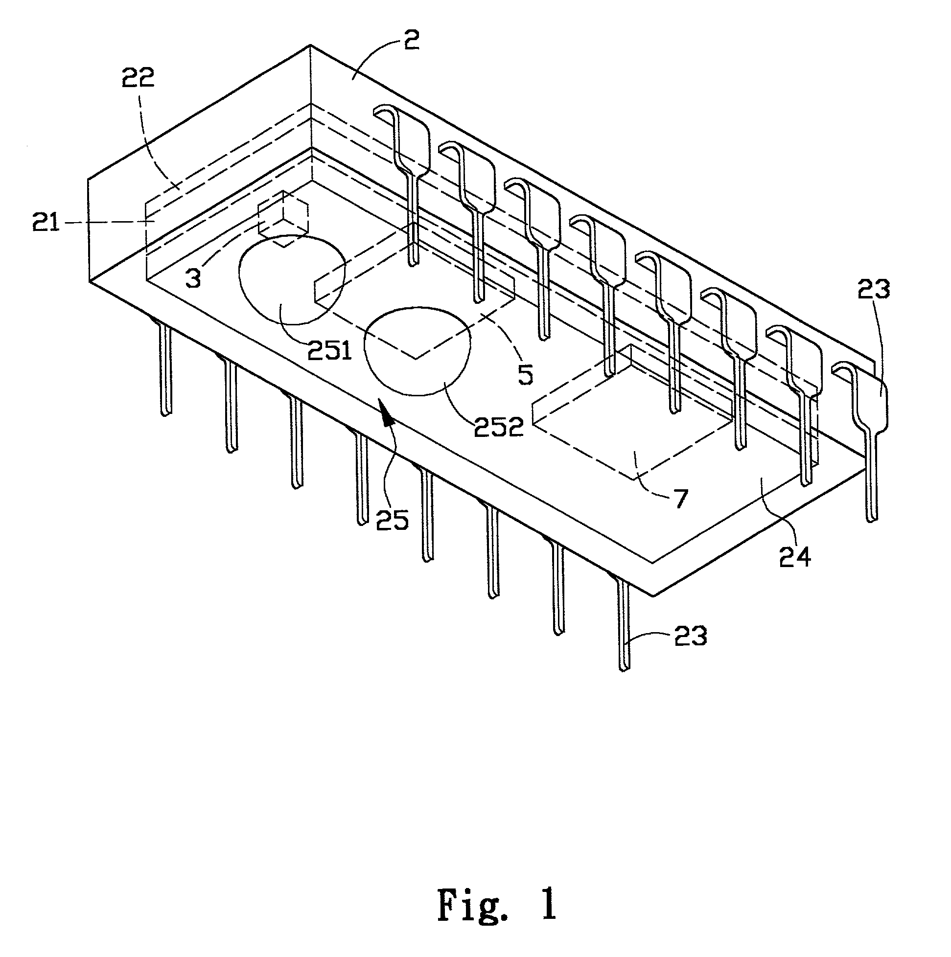
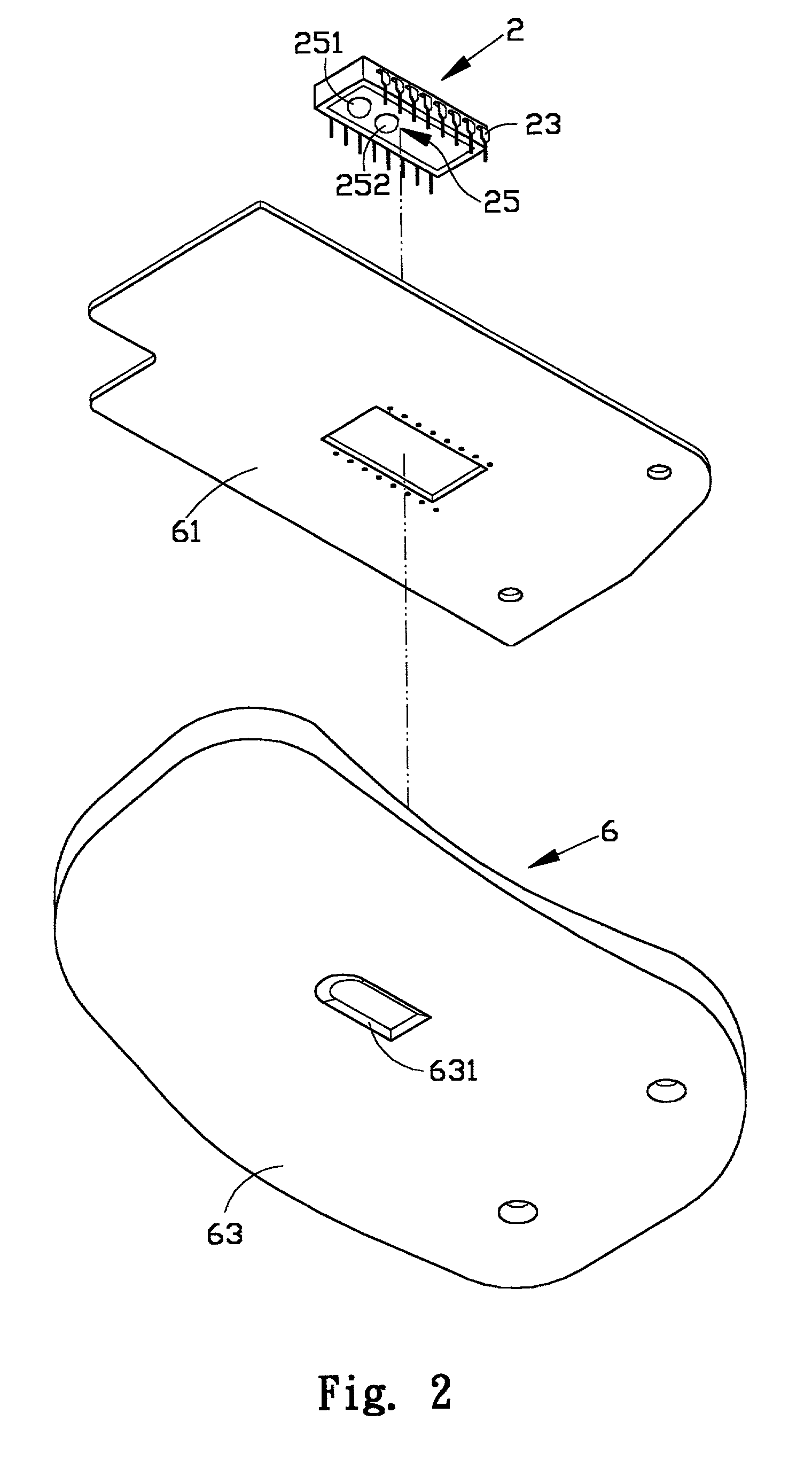
[0022] With reference to FIGS. 1, 2 and 3, the optical mouse in accordance with the present invention has a body 2, at least one LED 3 (light emitting diode), a sensor 5, an optical element 25 and at least one control element 7.

[0023] The body 2 has a predetermined space 21 defined inside the body 2 and having at least one lead 22 securely provided inside the space 21 and feet 23 each electrically connected to one of the feet 23.

[0024] The LED 3 is mounted inside the space 21 to electrically connect with the lead 22. The LED 3 is at the bottom of the body 2 and is able to emit visible light, infrared and the like.

[0025] The sensor 5 is received in the space 21 to electrically connect with the lead 22 and to correspond to the LED 3.

[0026] The optical element 25 is securely received in the space 21 and is composed of a first lens 251 adjacent to the LED 3 and a second lens 252 adjacent to the sensor 5. The first lens 251 and the second lens 252 are able to integrally formed with a cov...


PUM


Abstract

An optical mouse has a light emitting diode (LED) and a projecting lens located on a reflection path of the LED so as to project the light of the LED to the sensor. After the sensor picks up the signal from the LED, the signal is readily sent to the computer so as to simplify the structure and reduce the manufacturing cost of the optical mouse.

Description

[0001] 1. Field of the Invention[0002] The present invention relates to an optical mouse, and more particularly to a modulated optical mouse for a personal computer. The modulated optical mouse has a light emitting diode (LED), a sensing element and a projecting lens all of which are integrally formed into a module so as to simplify the structure of the optical mouse and reduce the cost.[0003] 2. Description of Related Art[0004] Normally, a computer mouse includes a housing composed of a top cover and a base. The base has a hole and a circuit board mounted on the base and having a tracking moduler corresponding to the hole and a wire connected to the host of the computer. The tracking moduler has a tracking ball. With such an arrangement, the movement of the tracking ball is able to be transformed into digital signal and sent to the host of the computer so as to accomplish the purpose of signal transmission. However, this kind of computer mouse needs to be connected to the host by m...

Claims


Application Information

Patent Timeline
IPC IPC(8): G06F3/03G06F3/033
CPCG06F3/0317
Inventor CHIN, YUAN-CHENG
Owner UNITY OPTO TECH CO LTD
Why Eureka
Try Eureka