System and method for utilizing a user non-perceivable light source in a machine

a non-perceivable light source and machine technology, applied in the field of machines, can solve the problems of ceramic heaters, higher cost and shorter warm-up times, and reliability problems in some ceramic heater designs

Inactive Publication Date: 2003-08-28
HEWLETT PACKARD DEV CO LP
View PDF0 Cites 13 Cited by
  • Summary
  • Abstract
  • Description
  • Claims
  • Application Information

AI Technical Summary

Problems solved by technology

While both of the ceramic heater and bulb heater fusers perform the desired fusing function in a toner imaging device, there are significant design trade-offs between the two.
Bulb heaters are characterized by lower cost, often better robustness and reliability, and longer warm-up times. Ceramic heaters are characterized by higher cost and shorter warm-up times. The brittle nature of ceramic, along with its other mechanical properties, may result in reliability issues in some ceramic heater designs.
This is due to the stresses of temperature cycling over many print jobs and the high pressures imparted by the pressure roller onto the ceramic substrate.
While illuminated components are desirable from functional and stylistic perspectives, they add to the cost of the machine into which they are incorporated.
The light produced by bulb heating elements is thus user non-perceivable.

Method used


Image

  • System and method for utilizing a user non-perceivable light source in a machine
  • System and method for utilizing a user non-perceivable light source in a machine
  • System and method for utilizing a user non-perceivable light source in a machine

Examples


Embodiment Construction

[0029] Illustrative embodiments and exemplary applications will now be described with reference to the accompanying drawings to disclose the advantageous teachings of the present invention.

[0030] While the present invention is described herein with reference to illustrative embodiments for particular applications, it should be understood that the invention is not limited thereto. Those having ordinary skill in the art and access to the teachings provided herein will recognize additional modifications, applications, and embodiments within the scope thereof and additional fields in which the present invention would be of significant utility.

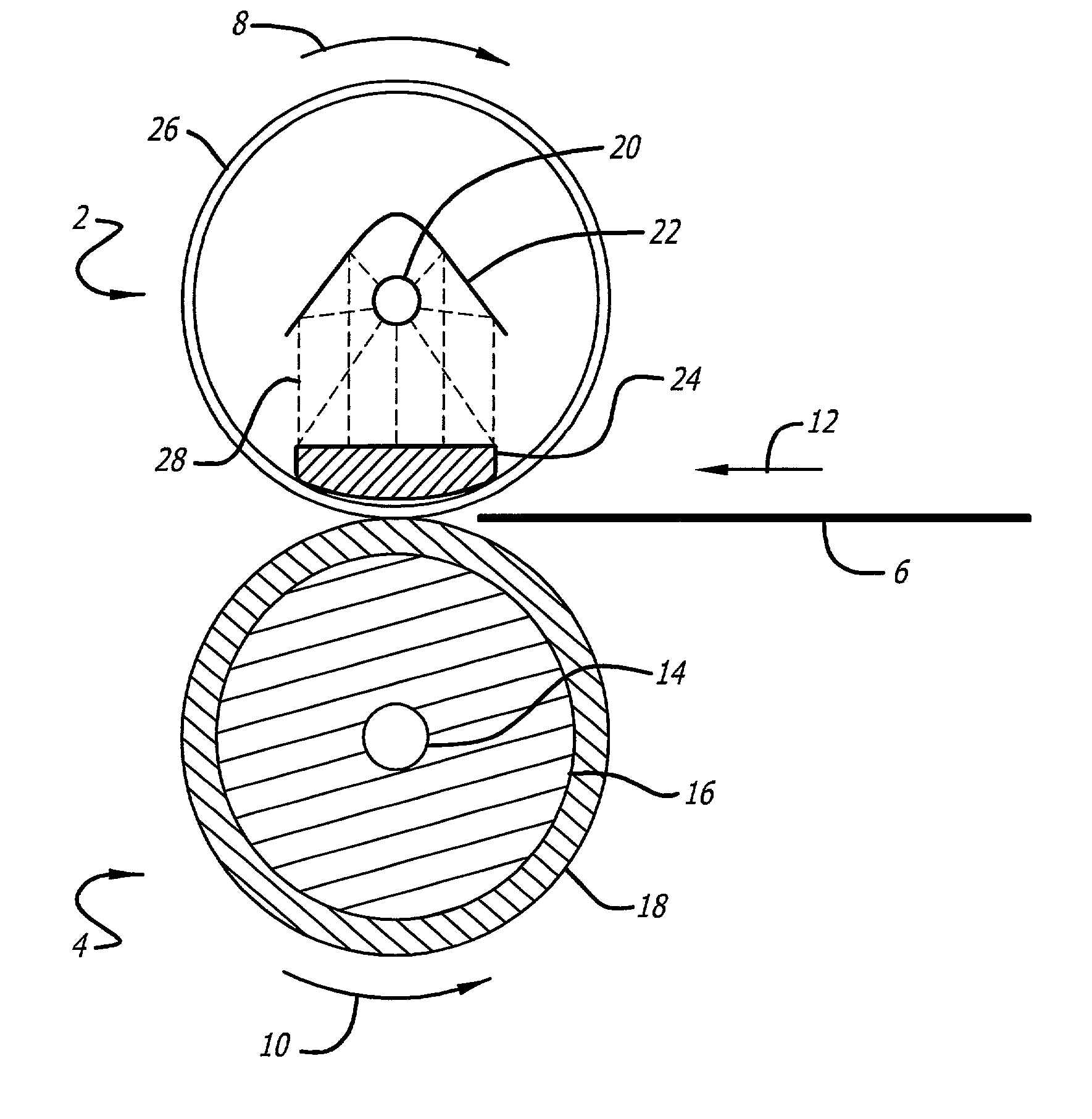
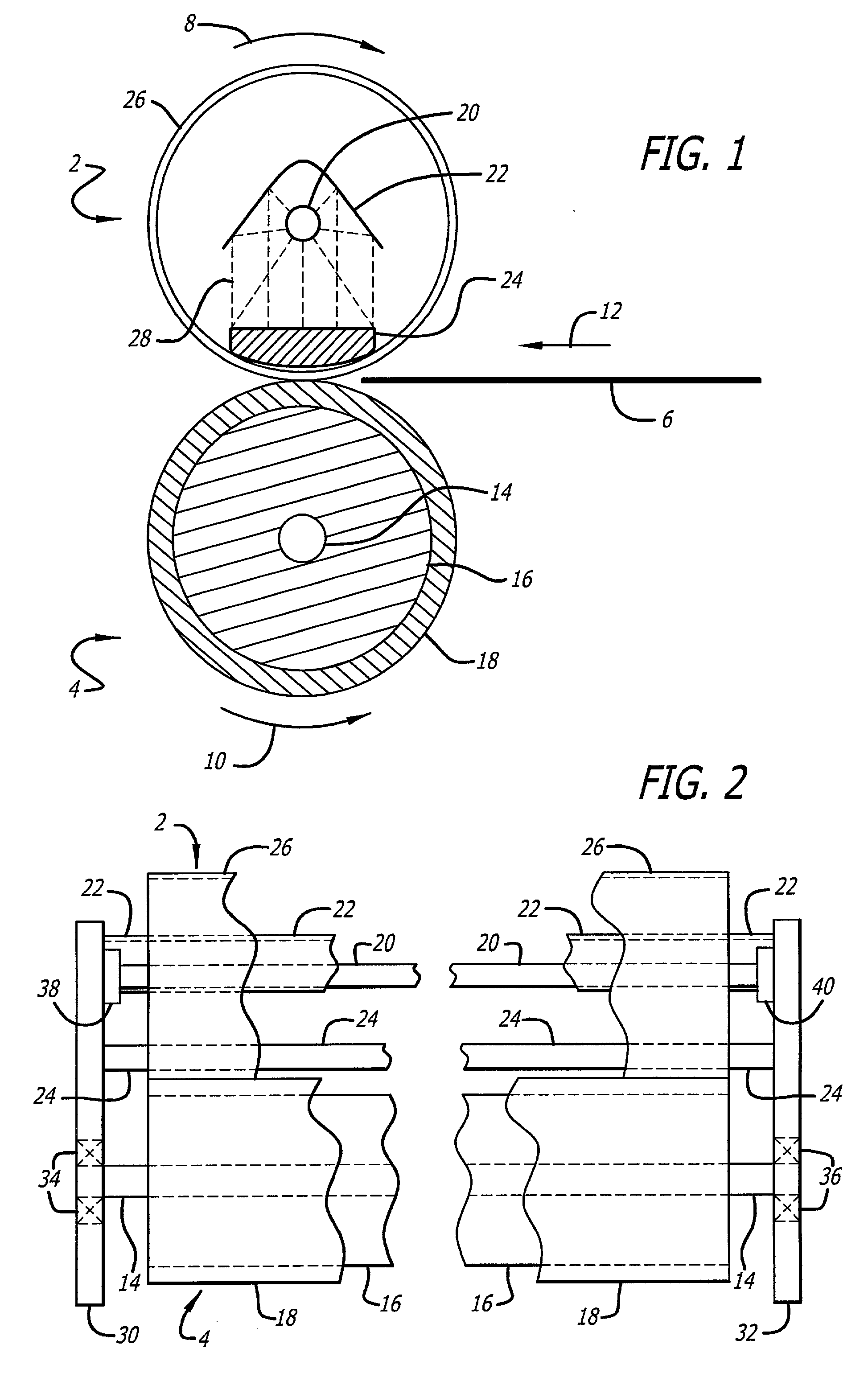
[0031] The present invention teaches and improved fuser for laser imaging systems including laser printers. The fuser unit includes a pressure roller and a fusing roller that operate as a pair or pinch rollers to both convey media and to fuse toner to the media using heat and pressure. In an illustrative embodiment, a parabolic (or other geometrica...


PUM


Abstract

A apparatus and method for fusing toner to media in a laser imaging device. A paraboloidal trough reflector is positioned about a linear heating element to focus and concentrate radiant energy emitted from the heating element onto a thermal spreader. The thermal spreader absorbs the radiant energy and converts it to heat. A thermoplastic fusing roller is rotatably supported about the bulb heater, the reflector and the thermal spreader. A pressure roller is supported to urge media against the fusing roller at the position of the thermal spreader. Fusing heat is conducted from the thermal spreader, through the fusing roller and to the media. The pressure roller is driven to rotate, thereby advancing the media through the fusing unit to fuse the toner thereto. Additionally, the present teachings disclose a printing device having a fusing unit with a bulb heater that emits user non-perceivable light. A mechanism is included for conveying light from the bulb heater to a location within the printing device. Also, a component positioned to receive the light and to utilize the light for illumination thereof in a user perceivable manner.

Description

[0001] 1. Field of the Invention[0002] The present invention relates to machines, including laser imaging and printing devices. More specifically, the present invention relates to toner-media fusing units used in laser imaging and printing devices and the use of the user non-perceivable light sources therein.[0003] 2. Description of the Related Art[0004] Laser printers and other imaging devices that employ toner transfer and toner fusing technology all rely upon a fusing unit to adhere toner particles, which form the image, to some type of media, such as paper. The fusing operation makes the toner-transferred image durable and permanent. Techniques used for toner fusing employ heat and pressure to fuse the toner particles to the media. Current fusing technologies employ a two-roller arrangement that utilize a pressure roller and a heating (or fusing) roller. The two rollers are urged together with a predetermined amount of force. At least one of the rollers is driven to rotate. The ...

Claims


Application Information

Patent Timeline
Patent Type & Authority Applications(United States)
IPC IPC(8): G03G21/00G03G15/20H05B3/00
CPCH05B3/0095G03G15/2053
Inventor ESKEY, ERIC UNGER
Owner HEWLETT PACKARD DEV CO LP
Why Eureka
Try Eureka