Imaging prevention method and system

a technology of infrared light and prevention method, applied in the field of imaging prevention method and system, can solve the problems of insufficient reflection ratio of infrared light in a conventional cinema screen, degrading the overall quality of visual images recorded through unauthorized means, and difficult to achieve desirable effects in a conventional system

Inactive Publication Date: 2003-11-06
SONY CORP
View PDF5 Cites 7 Cited by
  • Summary
  • Abstract
  • Description
  • Claims
  • Application Information

AI Technical Summary

Benefits of technology

[0009] (A) As a first means, the following technique is provided. In the technique, infrared light is projected to a viewer / audience direction from one or more infrared light projector means disposed at a screen side whereby enabling the infrared light to be incident into imaging means of a person conducting the unauthorized act. In embodiments of the present invention, the infrared light projector means may be realized in various configurations that include an infrared light projector apparatus, an infrared light projector, an infrared light emitting diode or any other device / apparatus / system capable of projecting infrared light. Furthermore, in embodiment of the present invention, the imaging means may be a camera, camcorder, video recorder or any other device / system comprising an image sensor capable of obtaining image data. The technique will eliminate needs of reflecting infrared light projected onto a screen surface of poor reflection ratio. Accordingly, the projected infrared light may be effectively incident into the imaging means of a person conducting the unauthorized act. That is, ample intensity of the infrared light may be radiated into the imaging means even when the low power infrared light projector apparatus is used.
[0010] (B) As a second means, another technique is provided. In the another technique, infrared light is actively reflected by an infrared light reflection means so as that the reflected infrared light may be incident into imaging means of a person conducting the unauthorized act. In embodiments of the present invention, the infrared light reflection means may be an infrared light mirror or any other device / apparatus / member capable of reflecting infrared light. The technique also will eliminate needs of reflecting infrared light projected onto a screen surface of poor reflection ratio. Accordingly, the projected infrared light may be effectively incident into the imaging means of a person conducting the unauthorized act. That is, ample intensity of the infrared light may be incident into the imaging means even when the low power infrared light projector apparatus is used.
[0012] (D) As a fourth means, still another technique is provided. In the still another technique, infrared light is selectively projected onto an area or areas of the screen surface, in which brightness is lower (for example, area or time period having a brightness of the screen surface equal or less than a predetermined value). The technique allows to emit or increase an amount of infrared light in a part where an amount of the visual image light is low whereby enabling to increase relative effects of the infrared light. Accordingly, more effective prevention of the visual image piracy may be possible. Further, in case that certain information is superposed on the infrared light, such information is surely recorded on the visual images illegally recorded.
[0013] (E) As a fifth means, still another technique is provided. In the still another technique, infrared light is projected from a plurality of infrared light projector means disposed in the vicinity of a screen whereby having the reflected infrared light be incident into imaging means of a person conducting the unauthorized act. The technique uses the similar principle as that of the conventional technique except the infrared light projector apparatus in the present embodiment are selectively disposed in the vicinity of the screen. Accordingly, the reflected infrared light may be significantly increased whereby enabling to promote the prevention effect further.

Problems solved by technology

In other words, an infrared light visual image, which is irrelevant to the main feature of visual images, is inevitably recorded on the visual image that is obtained in the unauthorized manner.
Accordingly, overall quality of visual images recorded through the unauthorized manner are degraded.
However, a reflection ratio of infrared light in a conventional cinema screen is not high enough.
Accordingly, it is difficult to materialize desirable effect in a conventional system described above because of the low reflection ratio in the cinema screen as well as lengthy infrared light path between the screen and the infrared light projector disposed at the vicinity of the visual image projector.
Further, there is a technical problem of that relatively high output power is required for the infrared projector so as to provide any significant effects on the visual images that are illegally recorded.
Alternatively, an emission intensity of infrared light may be frequently changed whereby enabling to degrade quality of visual images illegally recorded so much as that viewing of visual images recorded in the unauthorized manner becomes impossible due to the rapid change of intensity level.
Further, in case that certain information is superposed on the infrared light, such information is surely recorded on the visual images illegally recorded.
Further, this method does not exclude use of an object having a high infrared light reflection ratio, such as a wall or infrared light reflection mirror.
For example, in case in which scattered light of the infrared light which light flux is uniformly spread out is incident, an emission intensity of infrared light may be frequently changed whereby enabling to degrade quality of visual images so much as that viewing becomes difficult.
This case similarly enables to degrade quality of visual images so much as that viewing becomes difficult.
With utilizing the method, it would be difficult to view the visual images recorded in the unauthorized way since the infrared light is recorded onto the partial area with the low brightness.
This method does not control the infrared light emission based on the real-time detection results.
Particularly, it is more important for the infrared light projector means projecting to a corner portion of the screen since there is a possibility of that the infrared light may not be contributed in the prevention of the unauthorized act when the screen size is changed.

Method used


Image

  • Imaging prevention method and system
  • Imaging prevention method and system
  • Imaging prevention method and system

Examples


second embodiment example

[0173] (2) Second Embodiment Example

[0174] The second embodiment example is shown in FIG. 4. This embodiment example is related to a novel feature of projecting infrared light to a viewer / audience direction from a front side of the screen. FIG. 4 also shows an example applicable for a movie theater or other theater systems. Similar to the first embodiment example, the technique itself may be applicable to a home theater. Of course, the visual images projected onto the screen include television programs and the other copyrighted products as well as a movie. Next, a specific example of each apparatus composing the system shown in FIG. 4 will now be described. Here, an explanation of the projector apparatus 1 is omitted since it is similar to the first embodiment example.

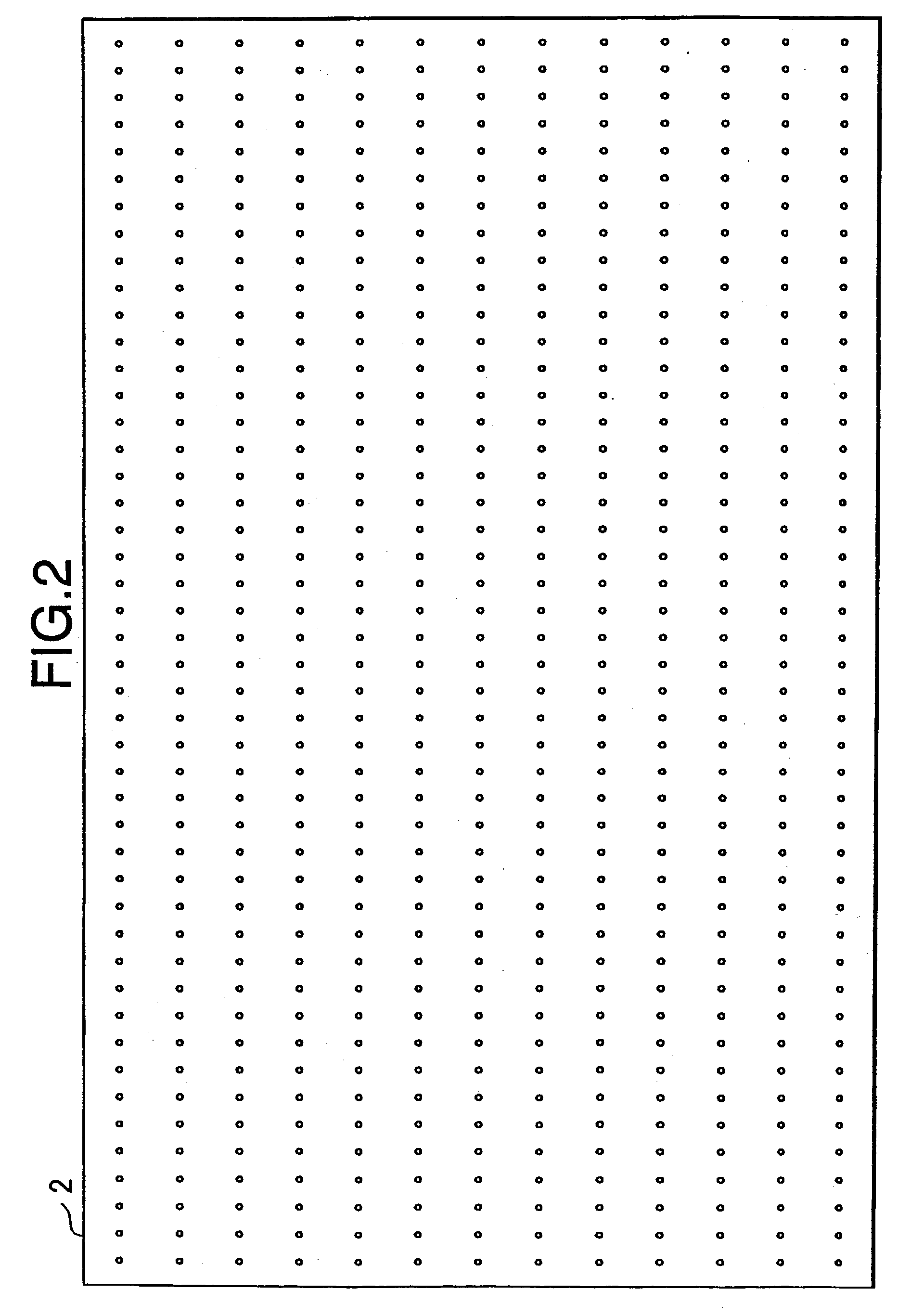
[0175] Contrary to the first embodiment example, the screen 2 may have any arbitrary construction. That is, the screen of FIG. 4 may be a screen having a configuration capable of easily transmitting the infrared light,...

third embodiment example

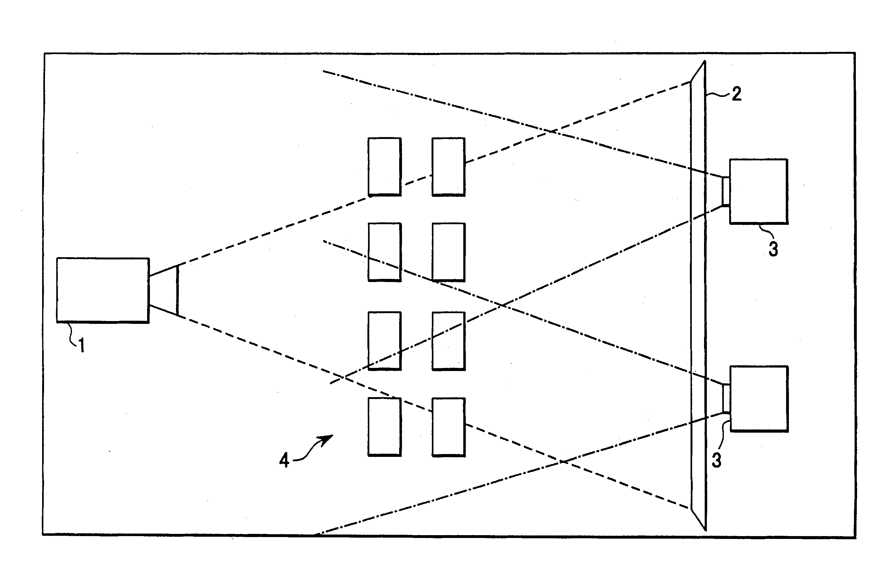
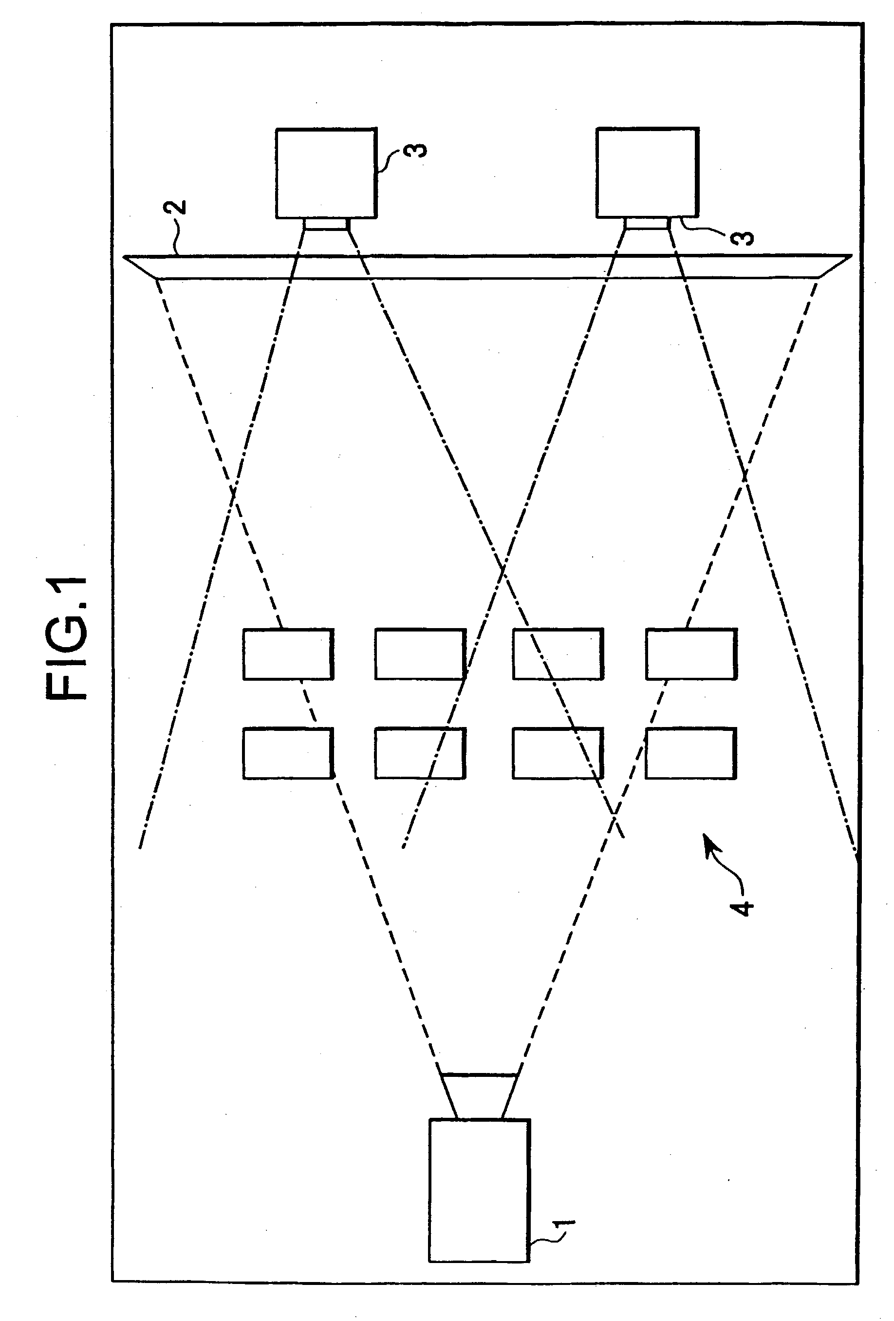
[0188] (3) Third Embodiment Example

[0189] The third embodiment example is shown in FIG. 5 and FIG. 6. This embodiment example is related to a novel feature of projecting infrared light to a viewer / audience direction from a side of the screen. FIG. 5 show an example of case in which the infrared light projector apparatus 3 is disposed outside (above) the top hem of the screen 2. FIG. 6 show an example of case in which the infrared light projector apparatus 3 are disposed outside (above) the top hem of the screen 2 and outsides of both left and right sides. All of figures shows application examples for the movie theater or any other theater system.

[0190] Similar to the first embodiment example, the technique itself may be applicable to a home theater. Of course, the visual images projected onto the screen include television programs and the other copyrighted products as well as a movie. Next, a specific example of each apparatus composing the system shown in FIG. 5 and FIG. 6 will now...

fourth embodiment example

[0203] (4) Fourth Embodiment Example

[0204] The fourth embodiment example is shown in FIG. 7. This embodiment example is related to a novel feature of projecting infrared light to a infrared light reflection mirror 5 having a high reflection ratio and for enabling the reflected light incident into the imaging apparatus of a person conducting the unauthorized act. In a system shown in FIG. 7, a reflection direction itself may be variable by driving the infrared light reflection mirror 5 with an actuator apparatus 6.

[0205] FIG. 7 shows an application example of a movie theater or any other theater systems. Similar to the first embodiment example, the technique itself may also be applicable to a home theater. Of course, the visual images projected onto the screen include television programs and the other copyrighted products as well as a movie. Next, a specific example of each apparatus composing the system shown in FIG. 7 will now be described. Here, an explanation of the projector app...


PUM


Abstract

As an imaging prevention method for interfering unauthorized imaging of visual image projected on a screen, there is employed a method for projecting infrared light to a viewer / audience direction from at least one or more infrared light projector means disposed at a rear side of the screen. According to the method, an amount of the infrared light directly is incident into an imaging apparatus whereby increasing the prevention effect since the more infrared light is directly incident into the imaging apparatus of a person conducting the unauthorized act.

Description

RELATED APPLICATION DATA[0001] This application claims priority to provisional application 60 / 291,414, and the disclosure of that application is incorporated herein by reference to the extent permitted by law.[0002] 1. Field of the Invention[0003] The present invention relates to technology for interfering unauthorized copy of visual images shown on a screen of a visual image system.[0004] 2. Description of the Related Art[0005] Following technique is disclosed as means to interfere such an unauthorized copy. The technique has been developed to utilize difference between visual characteristic of human eyes and image characteristic of imaging apparatus such as cameras, and employs infrared light to realize means to interfering the unauthorized copy. More specifically, infrared light is projected onto a screen surface from an infrared light projector disposed at a vicinity of an visual image projector or other remote position so as that infrared light reflected on the screen surface c...

Claims


Application Information

Patent Timeline
Patent Type & Authority Applications(United States)
IPC IPC(8): H04N5/74H04N5/913
CPCH04N5/74H04N2005/91392H04N5/913
Inventor KIMURA, KATSUMIKATAOKA, SHINYAZUSHI, NORIFUMIKUDO, YUKO
Owner SONY CORP
Why Eureka
Try Eureka