

Pedal assembly
- Summary
- Abstract
- Description
- Claims
- Application Information
AI Technical Summary
Benefits of technology
Problems solved by technology
Method used
Image

Examples
Embodiment Construction
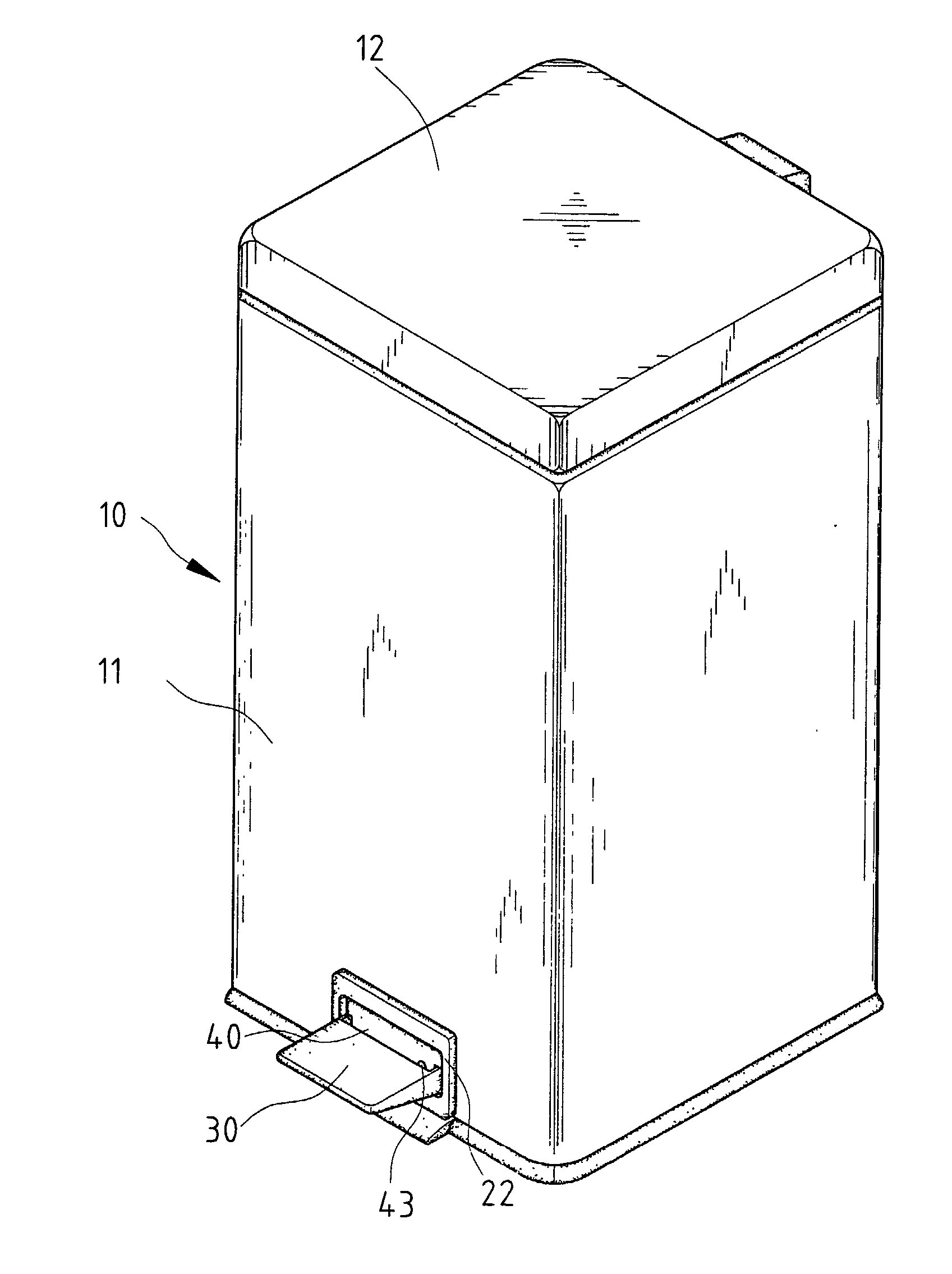
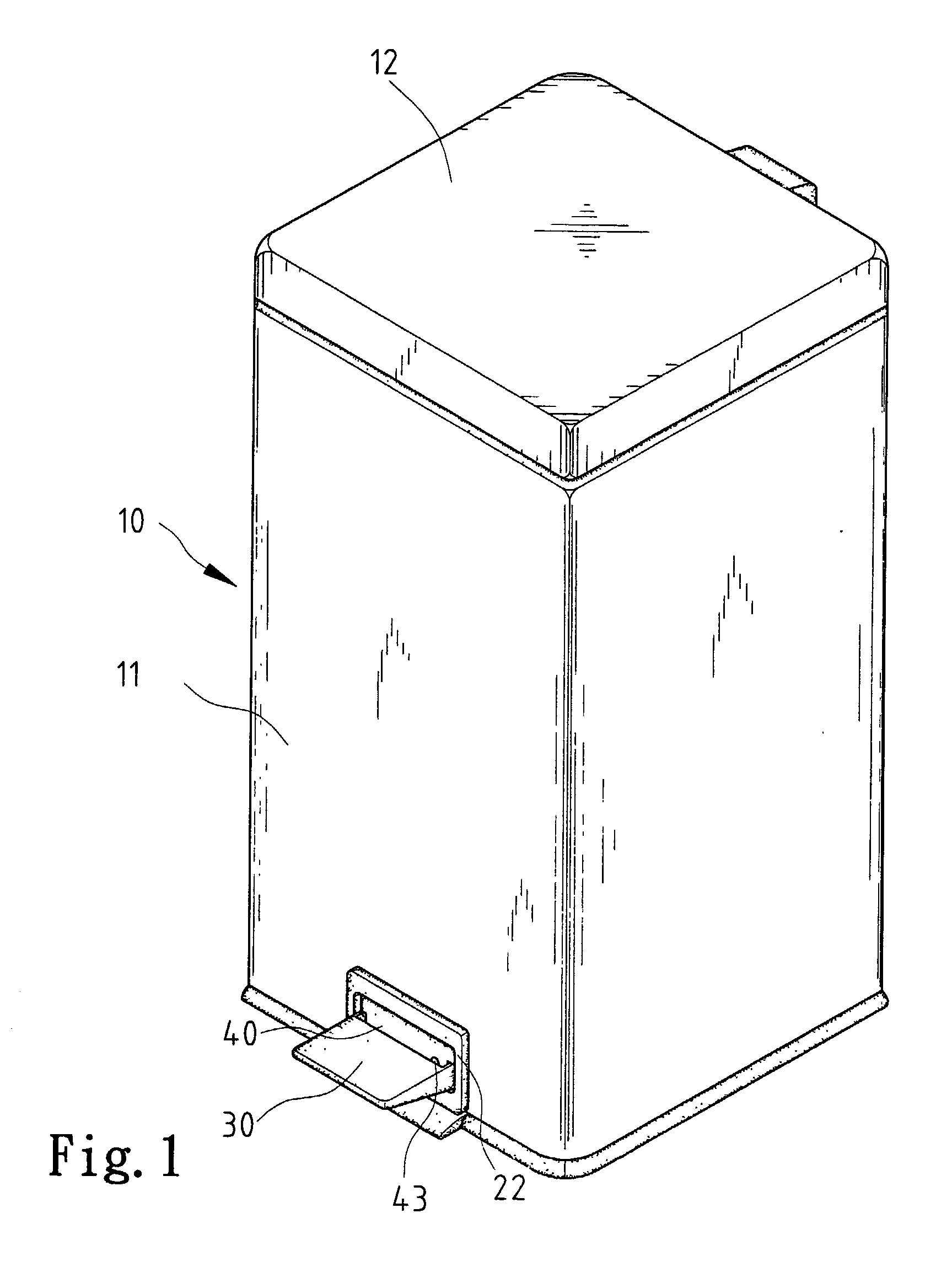
[0022] FIG. 1 shows a garbage-storing device 10 including a bin 11 and a cover 12 pivotally mounted on the bin 11. Referring to FIGS. 2.about.5, the cover 12 is linked to a pedal assembly according to the present invention via a linkage 13.
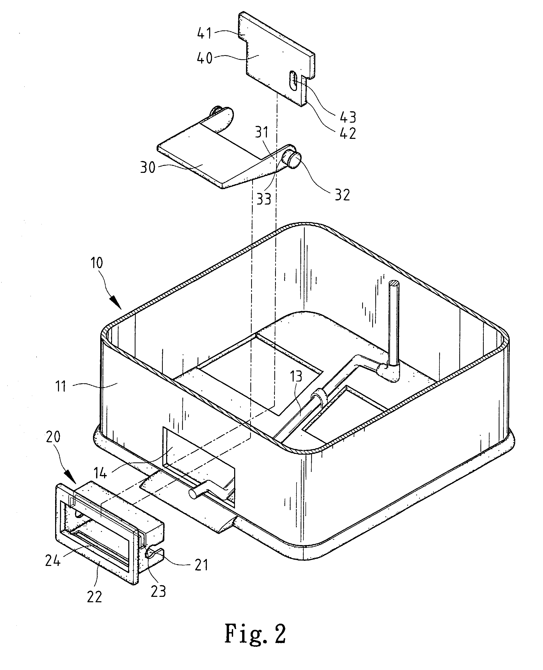
[0023] The pedal assembly includes a frame 20, a pedal 30 and a latch 40.
[0024] Referring to FIG. 2, the bin 11 defines an opening 14 through which a portion of the linkage 13 is inserted for contact with the pedal assembly.
[0025] Referring to FIG. 2, the frame 20 includes upper and lower plates and two side plates. Each of the side plates defines a cutout 21 extending horizontally. A slot 23 is cut into the upper plate and the side plates. A slot 24 is defined in the lower plate.
[0026] A flange 22 is formed on and around the frame 20.
[0027] The pedal 30 is formed with two ears 31. A shaft 33 is formed on each of the ears 31, and includes an enlarged head 32.
[0028] The latch 40 includes two edges from each of which a fin 41 extends and a lower edg...
PUM
 Abstract
Description
Claims
Application Information