Ink replenishing device, sub ink tank, and ink jet recording apparatus

a technology replenishing device, which is applied in printing and other directions, can solve the problems of paper dirty, large quantity, and other parts of ink jet recording apparatus

Inactive Publication Date: 2004-01-01
FUJIFILM BUSINESS INNOVATION CORP
View PDF6 Cites 32 Cited by
  • Summary
  • Abstract
  • Description
  • Claims
  • Application Information

AI Technical Summary

Problems solved by technology

Particularly, when the plenty of ink replenishment is carried out, the leaked ink is accumulated to become a large quantity, which sometimes caused other portions of the ink jet recording apparatus or paper to be dirty.

Method used


Image

  • Ink replenishing device, sub ink tank, and ink jet recording apparatus
  • Ink replenishing device, sub ink tank, and ink jet recording apparatus
  • Ink replenishing device, sub ink tank, and ink jet recording apparatus

Examples


Embodiment Construction

The present 0.378 125 31% Embodiment

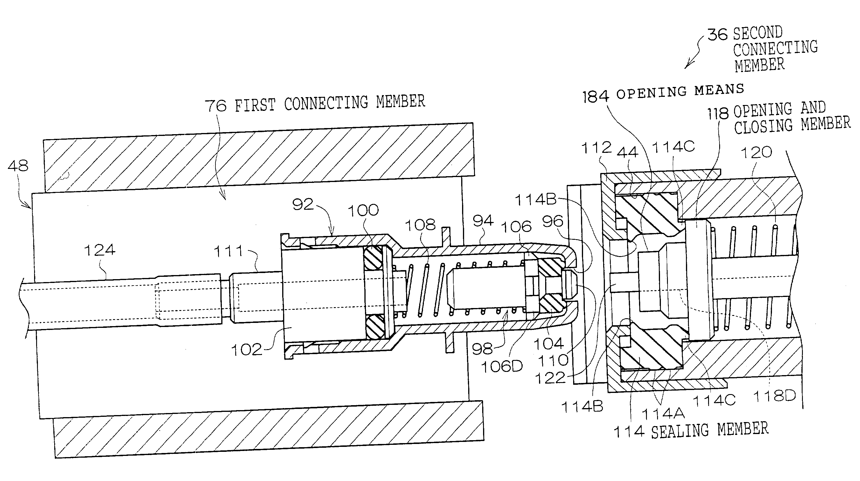
[0127] In Table 1, the values which are shown as the comparative example 1 are the ink leakage quantity in the ink replenishing device whose configuration is the same as the present embodiment except that the to-be-pressed piece 184 of the embodiment is not formed. In the ink replenishing opening 44 of the comparative example 1, as can be seen from FIG. 17, the periphery of the main body of the pipe 94 is at first closely contacted with the lip portion 114B and then the ink channel is formed in the pipe inserting process. Accordingly, the ink which is remained in or adhered to the outer peripheral portion of the main body of the pipe 94 or the inside of the ink replenishing opening 44 is not sucked into the sub ink tank 30 by the negative pressure in the sub ink tank 30. Further, in the case of the configuration of the comparative example 2 shown by the dash-double dot line in FIG. 17, the structure of the comparative example 2 is similar to that ...


PUM


Abstract

A port for replenishing ink on the side of a main ink tank advances and the nose or tip end of a main body of a pipe enters an ink replenishing opening on the side of a sub ink tank. When a valve body in the main body of the pipe and a valve on side of the sub ink tank are pressed with each other, a communicating port is opened by the valve body. When the main body of the pipe is further inserted into the ink replenishing opening, the valve is separated from a projection portion of a gasket, and a space therebetween starts to be widened. At this stage, as a lip portion of the gasket is not in contact with an outer peripheral portion of the main body of the pipe, an ink channel is opened to the atmosphere, the ink which is remained in or adhered to the outer peripheral portion of the main body of the pipe or an inside of the ink replenishing opening is absorbed into the sub ink tank dye ti a negative pressure in the sub ink tank. Namely, the present invention provides an ink replenishing device which can reliably prevent ink dirt from being caused by ink replenishing and an ink jet recording apparatus which is provided with the ink replenishing device.

Description

[0001] 1. Field of the Invention[0002] The present invention relates to an ink replenishing device for replenishing ink to a sub ink tank of a recording head device and an ink jet recording apparatus having the ink replenishing device.[0003] 2. Description of the Related Art[0004] In the ink jet recording apparatus in which an ink droplet is ejected on the basis of image information from a recording head to a recording medium such as paper to record an image, there is a configuration in which the sub ink tank corresponding to each recording head is mounted on a carriage scanning the recording head, various proposals regarding replenishing of ink to the sub-ink tank have been performed.[0005] For example, as shown in FIG. 21, an ink replenishing tank 540, having a tank holder 541 which rotates and descends as a stepper motor is rotated, is disclosed in Japanese Patent Application Laid-Open (JP-A) No. 10-202897. In this structure, a valve 546 having a hole for replenishing the ink, wh...

Claims


Application Information

Patent Timeline
Patent Type & Authority Applications(United States)
IPC IPC(8): B41J2/175
CPCB41J2/17523B41J2/17509
Inventor ODA, KAZUYUKIISHIZE, TATSUHIROTOMIKAWA, ICHIROAMARUME, KATSUSHIYONEYAMA, TAKESHI
Owner FUJIFILM BUSINESS INNOVATION CORP
Why Eureka
Try Eureka