

Telecine converting method
a converting method and telecine technology, applied in the field of telecine converting methods, can solve the problems of incompatibility of video and significant incompatibility of feeling
- Summary
- Abstract
- Description
- Claims
- Application Information
AI Technical Summary
Benefits of technology
Problems solved by technology
Method used
Image

Examples
second embodiment
[0067] [B] Description of Second Embodiment
[0068] [1] Description of Telecine Converting Method
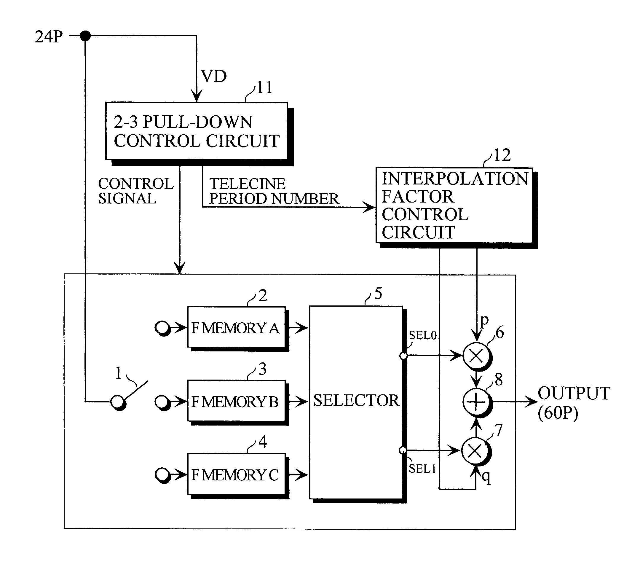
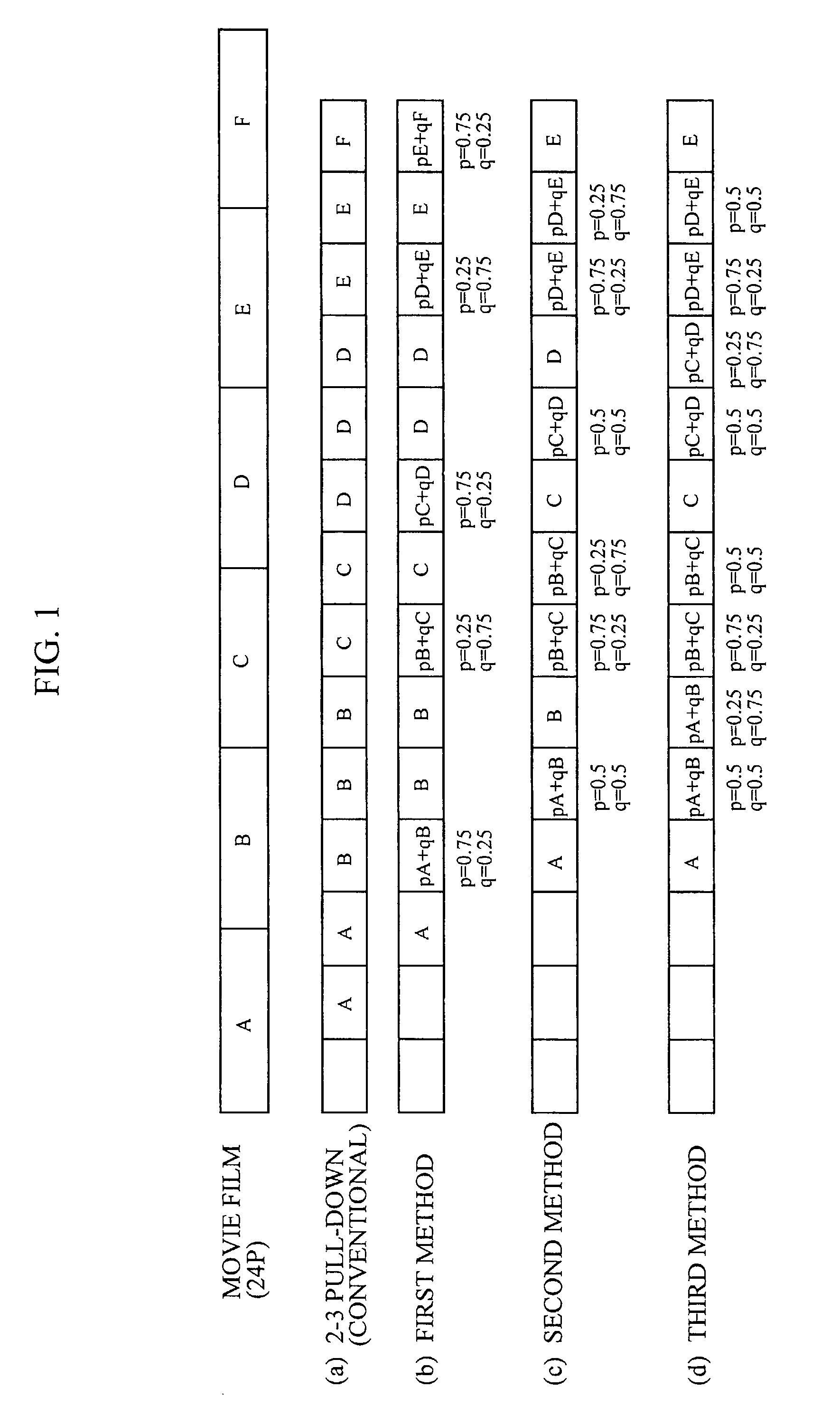
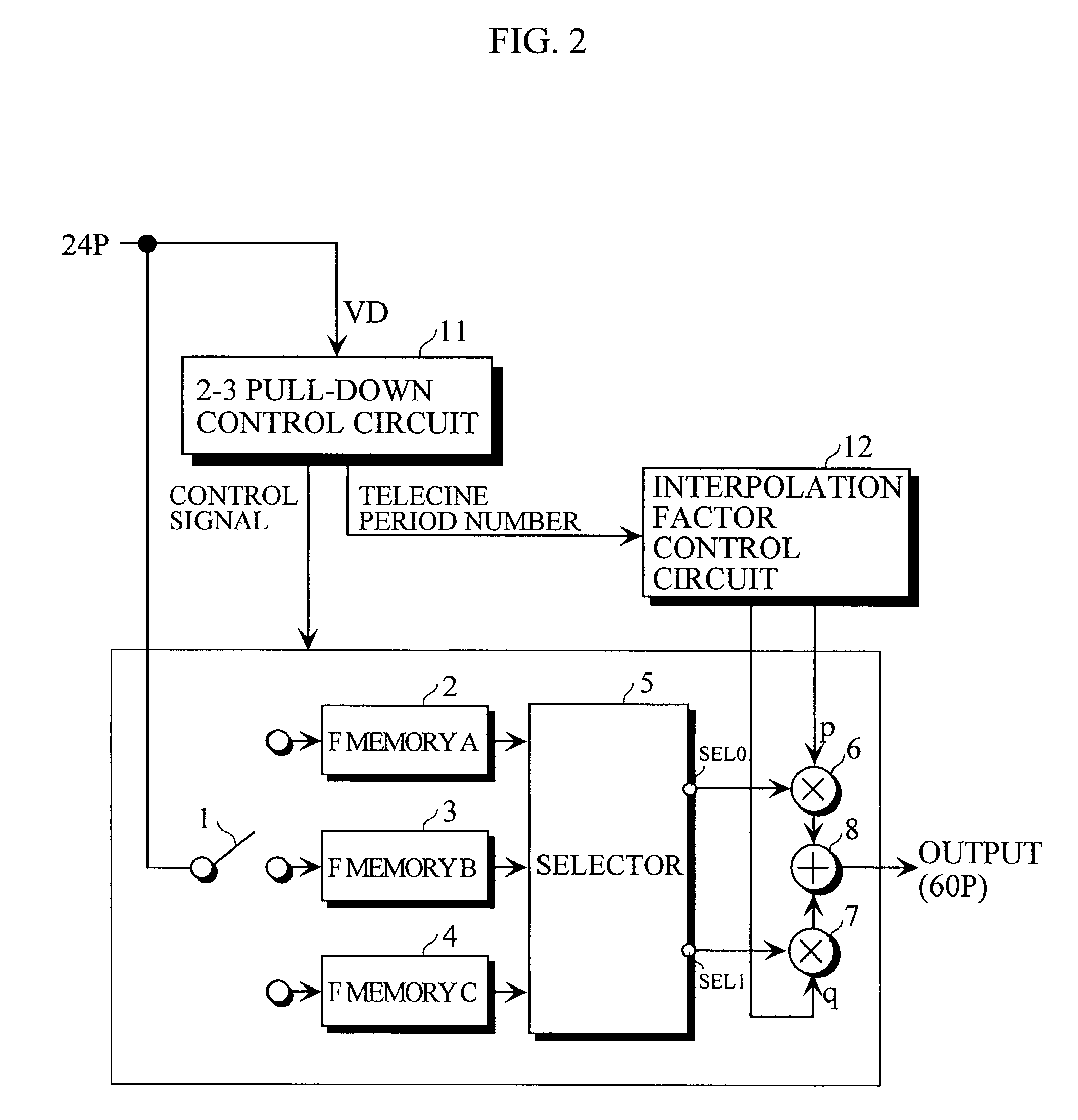
[0069] Description is made of a telecine converting method for converting a movie film composed of 24 frames per second (24P) into a progressive video signal composed of 60 frames per second (60P) using linear interpolation for each block in a screen.
[0070] In the second embodiment, telecine conversion is made by not the interpolation in the whole of the screen as in the first embodiment but finding interpolation factors for each block in the screen.
[0071] That is, the screen is divided into a plurality of blocks, to calculate for each of the blocks an interpolation factor on the basis of information related to the movement of a video in the block. In the present embodiment, the interpolation factors p and q for each pixel are calculated on the basis of the interpolation factor found for each of the blocks. An interpolated video is produced using the calculated interpolation factors p and ...
third embodiment
[0121] [C] Description of Third Embodiment
[0122] According to the first or second embodiment, the movement of a video becomes smoother than that in the conventional 2-3 pull-down system. When the video after telecine conversion is displayed on a CRT (Cathode-Ray Tube), it has become clear that flicker, that is, a phenomenon that a video seems to be flickering by the variation in the luminance level occurs depending on the type of the video.
[0123] The reason why the flicker occurs is conceivably that interpolation factors p and q the sum of which is one are used, so that the luminance level varies between a video obtained by interpolation and a video which is not interpolated. This will be more specifically described.
[0124] As shown in FIG. 17, a moving object (an oblique portion) X having a high luminance shall exist between a frame video A and a frame video B. The frame video A and the second frame video B are interpolated using two interpolation factors p and q the sum of which is...
fourth embodiment
[0157] [D] Description of Fourth Embodiment
[0158] In the fourth embodiment, interpolation factors are adaptively controlled depending on the area of a movement region. For example, an interpolated video is produced using factors p and q the sum of which is one when the area of the movement region is small, while being produced using factors p and q the sum of which is larger than one when the area of the movement region is large.
[0159] FIG. 21 illustrates the configuration of a telecine converter.
[0160] In FIG. 21, units corresponding to those shown in FIG. 19 are assigned the same reference numerals as those shown in FIG. 19.
[0161] The telecine converter shown in FIG. 21 differs from the telecine converter shown in FIG. 19 in that a movement information calculation circuit 13 is provided, and an interpolation factor control circuit 12 is switched between factors p and q the sum of which is one and factors p and q the sum of which is larger than one depending on the area of a moveme...
PUM
 Abstract
Description
Claims
Application Information