Low profile cardiac leads

Active Publication Date: 2004-01-22
OSCOR
View PDF3 Cites 98 Cited by
  • Summary
  • Abstract
  • Description
  • Claims
  • Application Information

AI Technical Summary

Benefits of technology

0017] To provide a solution to the problems and shortcomings associated with prior art endocardial leads, there is disclosed herein a novel multifilar conductor and method of making same. The novel multifilar conductor disclosed herein includes a plurality of jun

Problems solved by technology

However, defibrillation and pacing functions are not usually combined in one electrode.
Although the coaxial arrangement may provide enough electricity for multiple components at the distal end, the configuration also possesses considerable disadvantages.
If the covering is compromised, which is especially possible for long-term lead implantation, electrical communication between vital components will be compromised.
Also, the coaxial design increases the diameter of the lead, which may ultimately render potential applications risky or make incorporating all the desired components impossible.
Although this configuration reduces the potential for electrical crossover between conductors, it increases the profile of the lead and, in turn, the space needed for implantation of the lead, and incorporates the inherently less reliable stranded cable which may break due to fatigue or movement of the lead.
There are also pro

Method used


Image

  • Low profile cardiac leads
  • Low profile cardiac leads
  • Low profile cardiac leads

Examples


Embodiment Construction

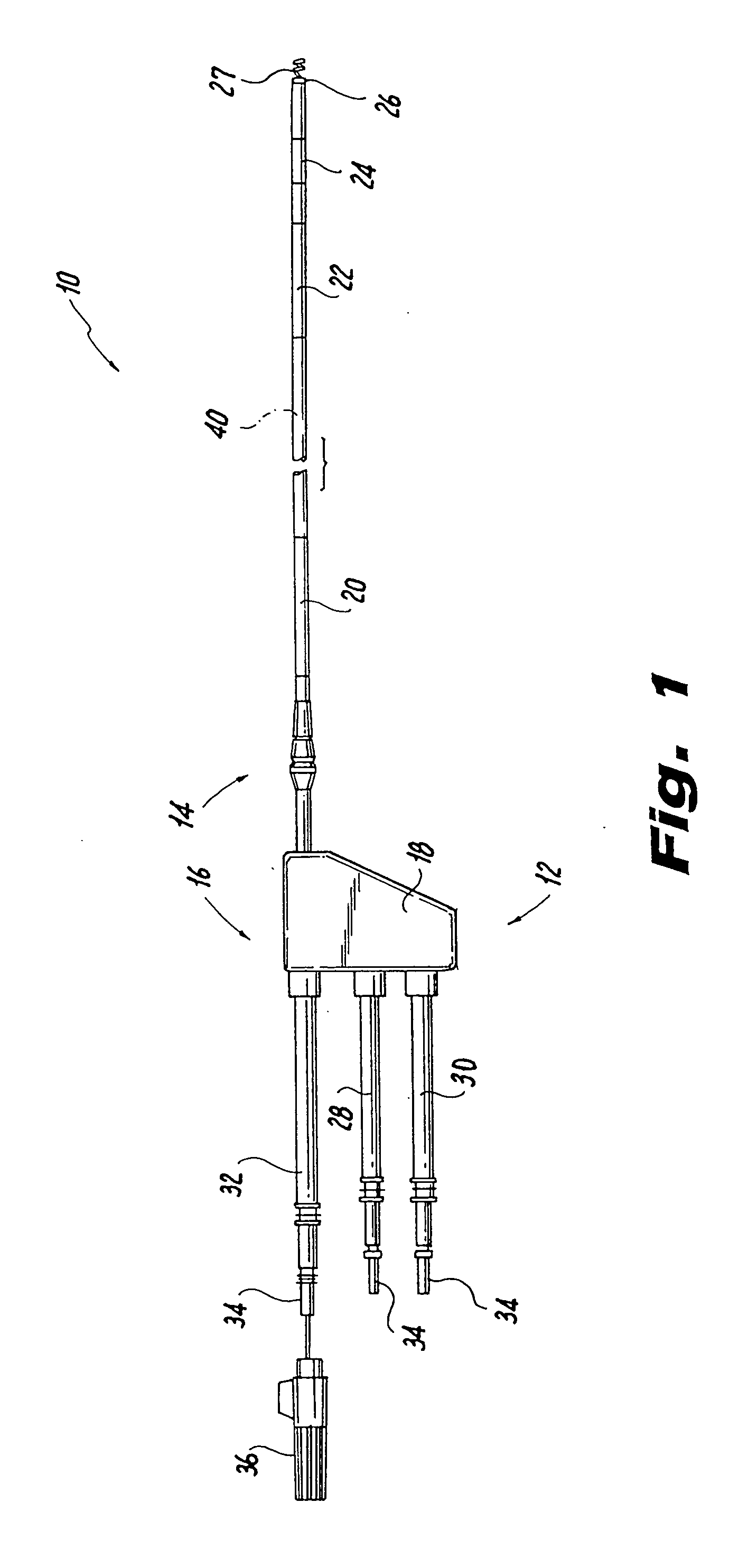
[0039] In the description which follows the term "proximal" refers to the end of the endocardial lead which is farthest from the surgical site, while the term "distal" refers to the end of the lead which is intended to be closest to the heart. In addition, in the following detailed description of the disclosure, whenever possible like reference numerals arebe used to identify similar structural elements of the invention disclosed herein.

[0040] Referring now to FIG. 1, an endocardial lead fabricated in accordance with the present disclosure is indicated generally by the reference numeral 10. Lead 10 includes an elongated support body or lumen 12 having a distal end portion 14 and a proximal end portion 16. Distal end portion 14 may be straight or have a pre-formed shape, such as a J-shape. Body 12 may include various joints, spacers, extensions and adapters to increase its operational length.

[0041] The distal end portion 14 of lead body 12 houses various electrical components used fo...


PUM


Abstract

A permanent implantable lead having an elongated lead body with a proximal end and a distal end. A multifilar conductor having electrically active elements for providing electrical communication between connectors at the proximal end and electrical components between the proximal and distal ends of the lead body, wherein hulls facilitate resilient, low profile, efficient connection between the multifilar conductor and electrical components and seals secure the position of the electrical components. The hulls are located radially outward of the conductor and radially inward of the electrical components and the seals are located radially outward of the electrical components.

Description

CROSS-REFERENCE TO RELATED APPLICATION(S)[0001] The subject application is a continuation-in-part of commonly owned, co-pending U.S. patent application Ser. No. 10 / 192,043, filed Jul. 10, 2002, the disclosure of which is herein incorporated by reference.[0002] 1. Field of the Invention[0003] The present disclosure relates generally to cardiac pacing and defibrillation leads, and more particularly, to a low profile cardiac leads having a single lumen and a multifilar conductor coil.[0004] 2. Background of the Related Art[0005] It is well known in the field of cardiology that certain types of cardiac arrhythmia can be effectively treated by the application of electrical energy to cardiac tissue in an attempt to restore a normal sinus rhythm. Endocardial leads implanted within the heart have been developed to monitor the cardiac state and automatically deliver electrical energy to cardiac tissue. These leads sense the intrinsic rhythm, atrial and ventricular tachycardia and atrial and ...

Claims


Application Information

Patent Timeline
IPC IPC(8): A61N1/05
CPCY10S439/909A61N1/056
Inventor OSYPKA, THOMAS P.VAN DEN NIEUWENHOF, RONALD A.ISLAM, MOHAMMED
Owner OSCOR
Why Eureka
Try Eureka