
Device to assist propulson of hand-propelled vehicles

a technology for propulsing vehicles and hand-propelled vehicles, which is applied in the direction of mechanical control devices, hand carts, controlling members, etc., and can solve problems such as injury to operators, significant problems, and spinal column injuries

Inactive Publication Date: 2004-02-12
DUNBAR KENNETH BARRIE
View PDF7 Cites 5 Cited by
  • Summary
  • Abstract
  • Description
  • Claims
  • Application Information

AI Technical Summary

Benefits of technology

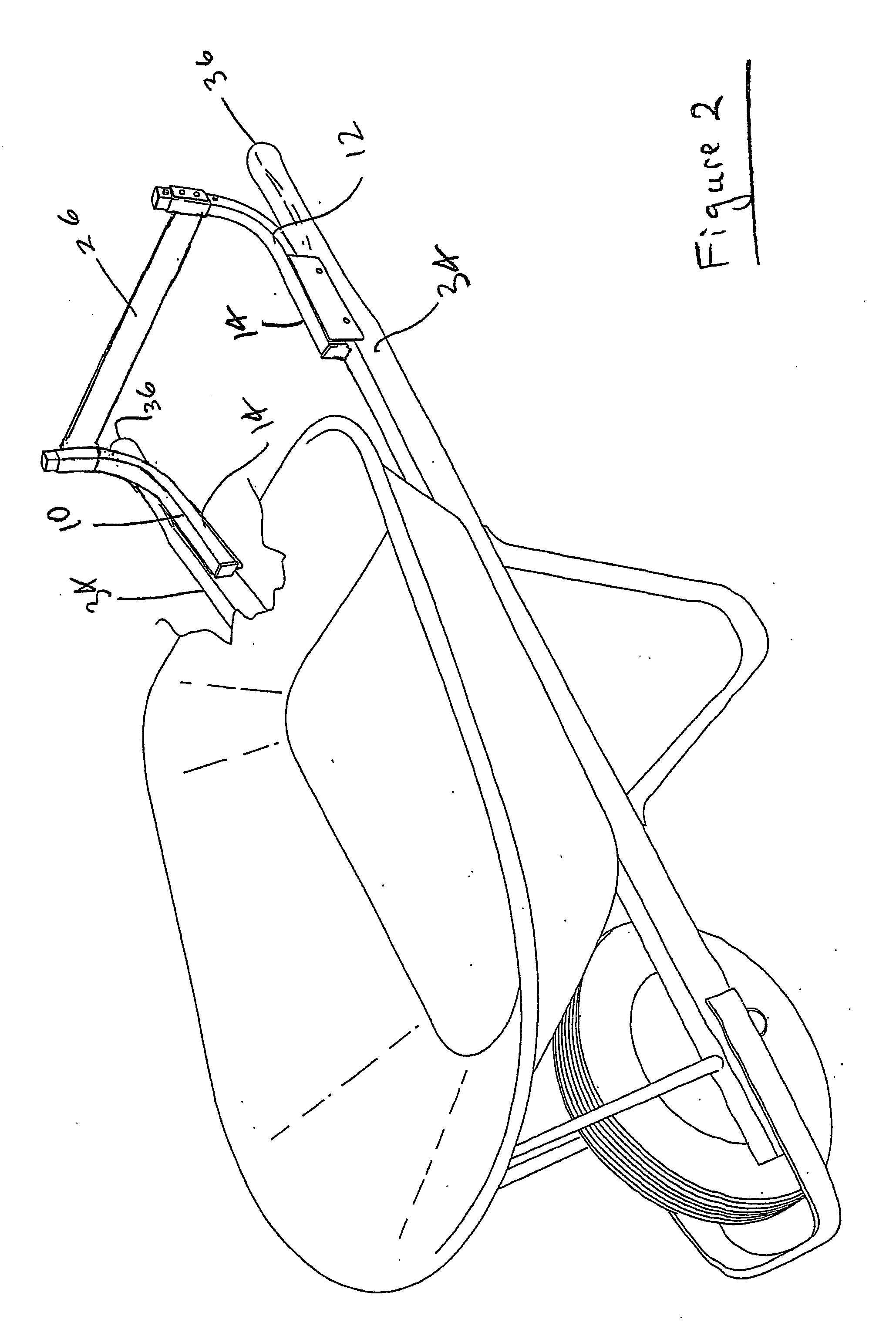
[0010] Preferably, the spine / arm, structure still supports the wheelbarrow when travelling and steering, but this task is more easily and safely achieved as there is preferably less compression on the spine, and the spine is not inclined as far forward as it may be without the use of the aid. Balance against sideways tilting can preferably also be controlled by the hips also, rather than primarily through the arms and shoulders.

Problems solved by technology

When dealing with vehicles as defined above, a significant problem can occur when attempting to push a large load.
Due to the design of the conventional wheelbarrow, the manner in which supporting, propelling, restraining and balancing forces are transmitted between the operator and the wheelbarrow have often resulted in injury to the operator.
Such injuries include lower back strain; shoulder strain, and damaged: muscles, tendons or ligaments including those in arms and hands.
In particular, injuries can occur to the spinal column.
Attempts have previously been made to improve the use of wheelbarrows, though these attempts have not been universally satisfactory.
Use of such as strap can be inconvenient at times, and may be difficult to effectively engaged, especially by an inexperienced operator.
Though this arrangement assists in supporting the barrow, it can be inconvenient or counterproductive in assisting to push or pull the wheelbarrow.

Method used


Image

  • Device to assist propulson of hand-propelled vehicles
  • Device to assist propulson of hand-propelled vehicles
  • Device to assist propulson of hand-propelled vehicles

Examples


Embodiment Construction

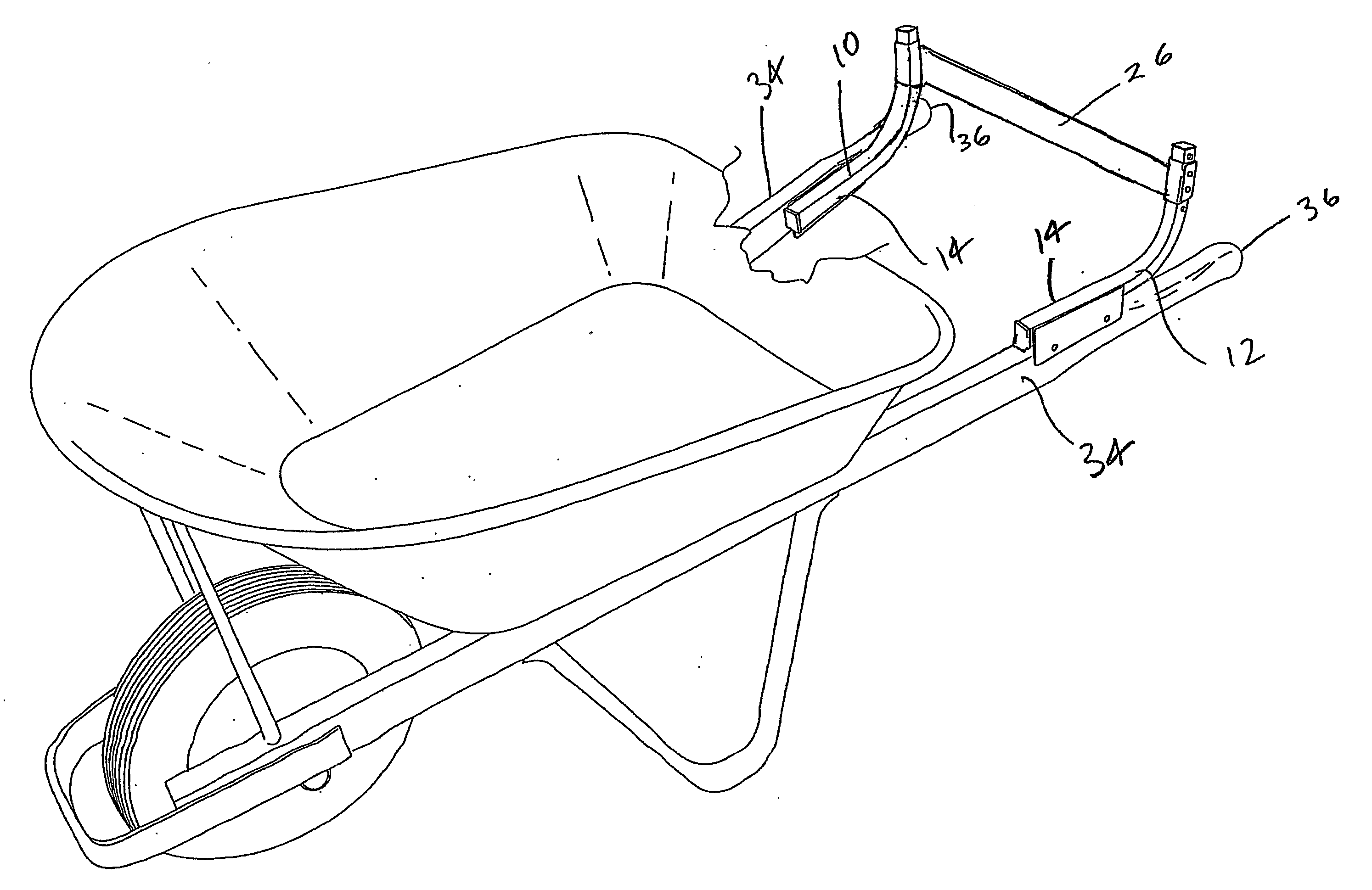
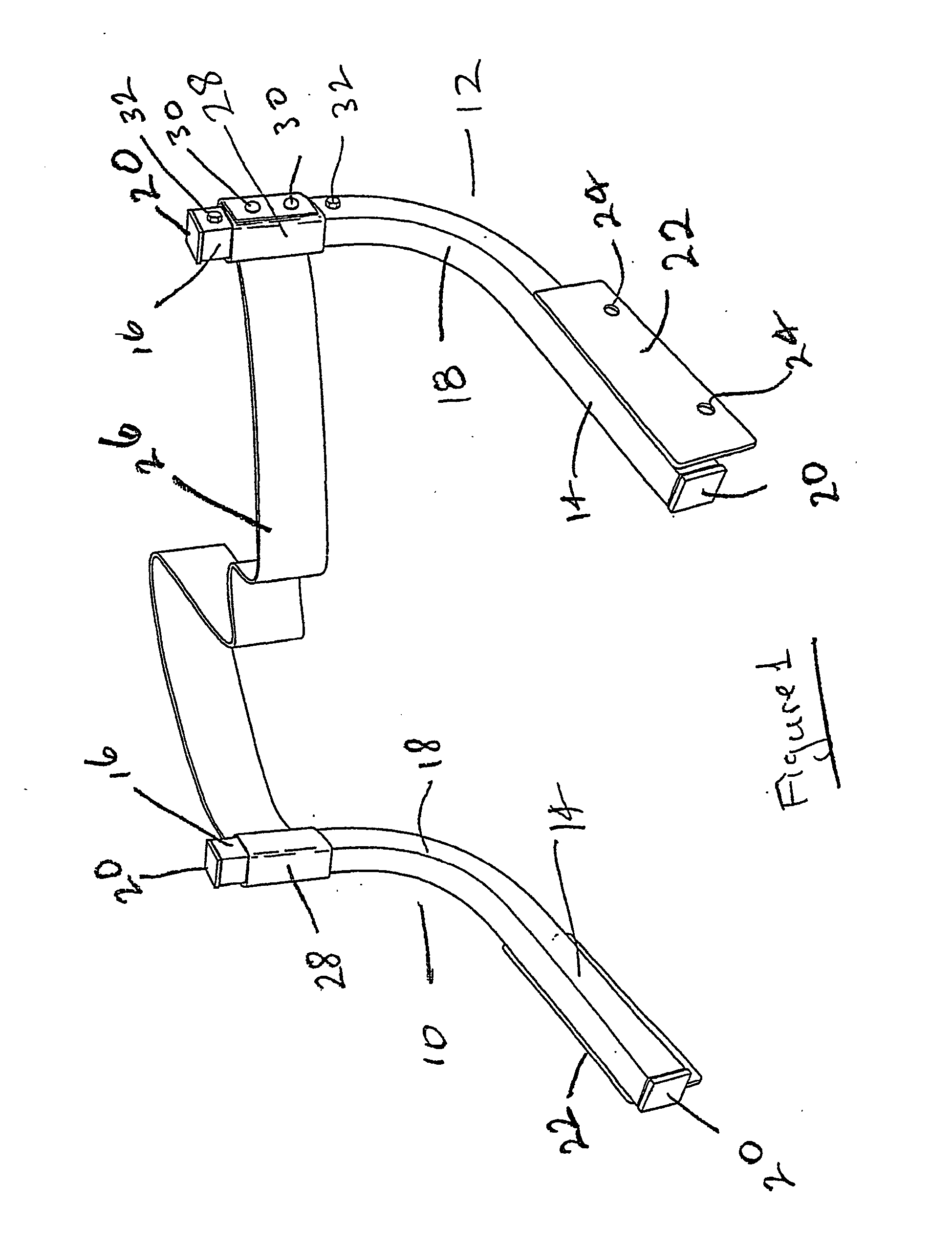
[0020] To refer to FIGS. 1 and 2, there is shown a device for assisting in the propulsion of a vehicle, the device having two arms 10, 12. Each of the arms 10, 12 has a generally horizontal portion 14 and an upright portion generally designated as 16 with there being an arcuate portion 18 connecting the horizontal portion 14 and upright portion 16. The three portions 14, 16, 18 are preferably integral. To show they are made from a square-section metal extrusion, although this is only preferred and not essential. End caps 20 may be provided, if desired, so as to protect a user from any rough or raw edges.

[0021] Securely attached to the horizontal portion 14, preferably on an outer side thereof, is a connecting means 22 which, in this instance, is in the form of a flat plate. The plate 22 may be attached to the horizontal portion 14 by any suitable means such as, for example, bolts, screws, welding, gluing, or otherwise, as desired. Furthermore, it may be possible for it to be made in...


PUM


Abstract

A device with two arms (10, 12) in spaced-apart relationship for secure attachment to a wheel-barrow. A member (26) extends between the two arms (10, 12) and is engaged by an operator contacting the member (26) with their hip / waist area to assist in propelling the wheel-barrow.

Description

[0001] This invention relates to a device to assist propulsion of hand propelled vehicles and refers particularly, though not exclusively, to a device attachment to arms of vehicles such as a wheelbarrow to assist in the propulsion of the wheelbarrow.DEFINITIONS[0002] Throughout this specification, reference to a vehicle is to be reference to a hand propelled vehicle including such devices as wheelbarrows, trolleys, hand-trucks, perambulators, push chairs, wheelchairs, or the like where the primary propulsion is by human endeavour pushing the vehicle.BACKGROUND TO THE INVENTION[0003] When dealing with vehicles as defined above, a significant problem can occur when attempting to push a large load. This can quite often happen when, for example, pushing a wheelbarrow full of bricks, cement, or other heavy load, particularly up an inclined slope.[0004] The wheelbarrow in concept and execution has changed very little. Lighter and stronger materials have been incorporated into its design ...

Claims


Application Information

Patent Timeline
Patent Type & Authority Applications(United States)
IPC IPC(8): B62B1/18B62B5/06
CPCB62B1/18Y10T74/20738B62B5/068
Inventor DUNBAR, KENNETH BARRIE
Owner DUNBAR KENNETH BARRIE
Learn More