
Method for driving an liquid crystal display in a dynamic inversion manner

a liquid crystal display and dynamic inversion technology, applied in the direction of instruments, static indicating devices, etc., can solve the problems of flicker problems, power consumption dependent, flicker problem becoming worse, and both of them also have flicker problems

Active Publication Date: 2004-02-19
HANNSTAR DISPLAY CORPORATION
View PDF9 Cites 46 Cited by
  • Summary
  • Abstract
  • Description
  • Claims
  • Application Information

AI Technical Summary

Problems solved by technology

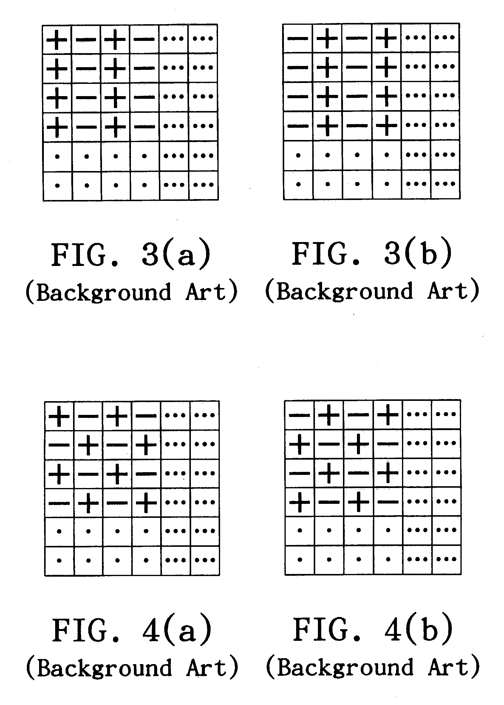
Unfortunately, both of them also have flicker problems.
But power consumption is dependent on the frequency of the AC electrical field.
Therefore, the flicker problem becomes worse.
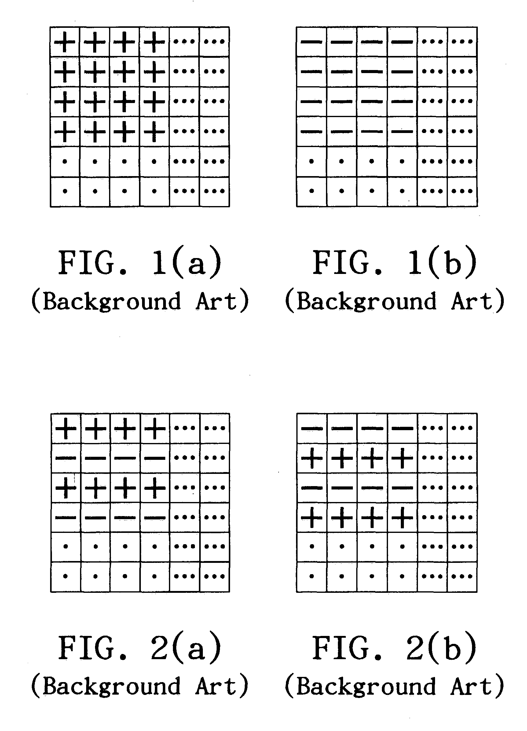
The aforementioned conventional driving methods of polarity inversion also have flicker problems during the displaying of a specific test pattern.
An LCD panel using a row inversion method has flicker defects during the displaying of a horizontal-line test pattern.
A user with sensitive vision is likely to detect the same problem.
In this configuration of the LCD panel, more non-display space is needed and leads to an increase in manufacturing costs.

Method used


Image

  • Method for driving an liquid crystal display in a dynamic inversion manner
  • Method for driving an liquid crystal display in a dynamic inversion manner
  • Method for driving an liquid crystal display in a dynamic inversion manner

Examples


Embodiment Construction

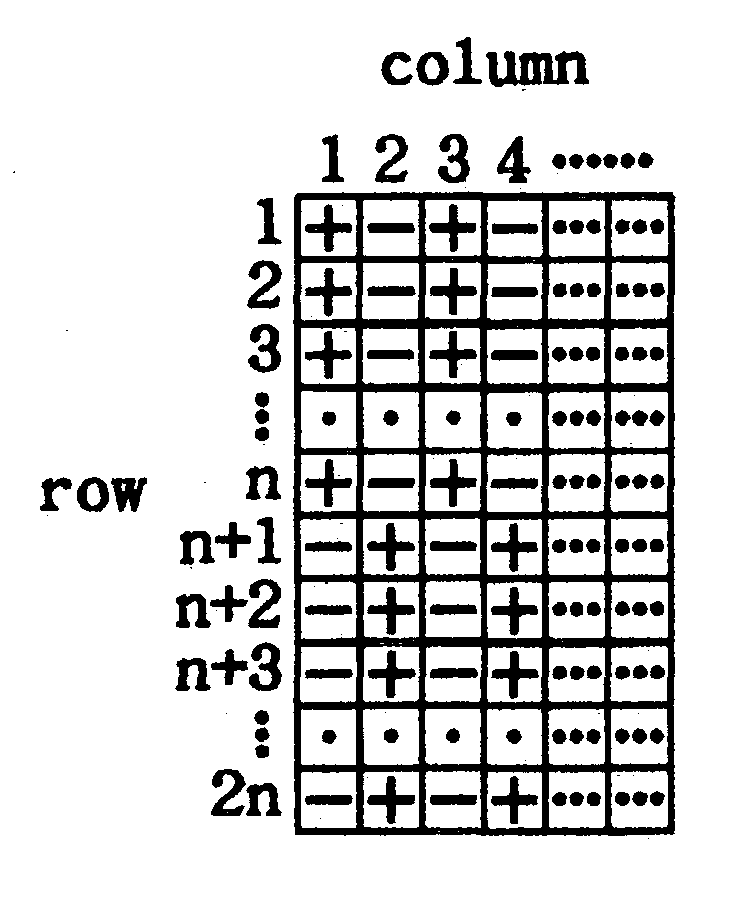
[0030] FIGS. 5(a)-5(e) are diagrams for explaining the generating procedure of polarity blocks in accordance with the present invention. First, a polarity frame is divided into a plurality of polarity blocks with the same area along the scanning lines, and each of the polarity blocks has the same even number of scanning lines. As shown in FIG. 5(a), the polarity block covers 2n pieces of scanning lines. For example, a XGA LCD panel fifteen inches in size has 768 scanning lines, wherein each scanning line is connected to 1,024 pixels. If n is equal to two, the XGA LCD panel is divided into 192 polarity blocks. Each polarity block covers four scanning lines. To simplify the driving circuit of an LCD panel, every polarity block in a polarity frame (or a polarity pattern) has the same polarity configuration. When n is equal to two, the driving method is called a 2-line mode dynamic inversion. If n is equal to three, the driving method is called a 3-line mode dynamic inversion. We explai...


PUM


Abstract

A driving method is used for driving a liquid crystal display in a dynamic inversion manner. First, a polarity frame is divided into a plurality of polarity blocks with the same area along scanning lines. By a DC balance requirement as the prerequisite, the polarities of one half of the pixels, total n, connected to the same signal line of one polarity block, are positive, and the polarities of other half of the pixels are negative. Polarity patterns, total 2n frames, are generated from sequentially shifting one polarity line to the next polarity line and shifting the bottom polarity line to the top polarity line in each polarity block. Polarity patterns are arranged in a polarity inversion group in a sequence. During a period of the polarity inversion group, each of the polarity patterns separately appears one time for inverting the polarities of the pixels to avoid a flicker image under the displaying of a specific test pattern.

Description

[0001] 1. Field of the Invention[0002] The present invention relates to a method for driving a liquid crystal display (LCD), and more particularly to a method for driving an LCD panel employing a dynamic inversion manner.[0003] 2. Description of the Related Art[0004] The image quality of LCDs deteriorates due to a flicker phenomenon, which is directly relative to the sensitivity of naked eyes. Thin film transistor LCDs (TFT-LCDs) and super twisted nematic LCDs (STN-LCDs) are now generally used for display apparatuses. Unfortunately, both of them also have flicker problems. In most cases to avoid flicker images, LCDs must be driven in an AC electrical field, because polarity inversion is needed. In LC cells, we find that flicker is mainly caused by the mobile ion charges. Even though a higher frequency AC applied to the LC cells can reduce the flicker phenomenon. But power consumption is dependent on the frequency of the AC electrical field. On the other hand, due to a stray capacito...

Claims


Application Information

Patent Timeline
IPC IPC(8): G09G3/36
CPCG09G2320/0247G09G3/3614
Inventor PAI, FENG-TING
Owner HANNSTAR DISPLAY CORPORATION
Learn More