Spatial and temporal selective laser assisted fault localization

a laser assisted fault and spatial and temporal technology, applied in the field of spatial and temporal selective laser assisted fault localization, can solve the problem that devices such as dynamic logic devices cannot be held in a static state for a long time for scanning and measurement to be completed, and achieve the effect of reducing the number of errors and avoiding the effect of affecting the accuracy of the results

Active Publication Date: 2005-11-22
DCG SYST
View PDF9 Cites 38 Cited by
  • Summary
  • Abstract
  • Description
  • Claims
  • Application Information

AI Technical Summary

Problems solved by technology

However, devices such as dynamic logic devices generally cannot be held in a static state sufficiently long for the scanning and measurement to be completed.

Method used


Image

  • Spatial and temporal selective laser assisted fault localization
  • Spatial and temporal selective laser assisted fault localization
  • Spatial and temporal selective laser assisted fault localization

Examples


Embodiment Construction

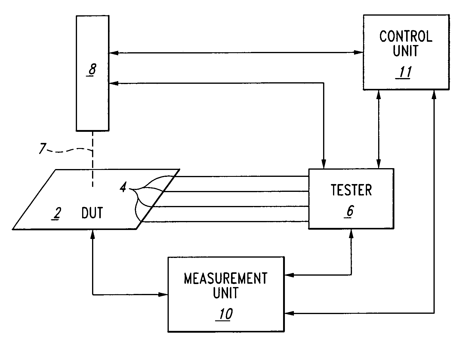
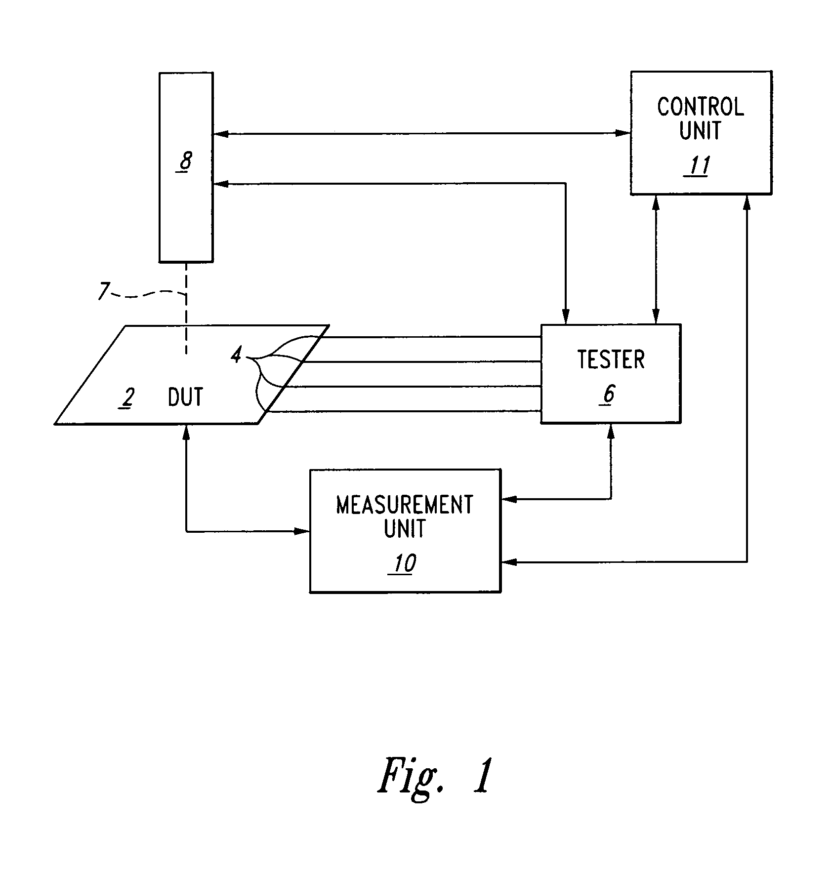
[0021]Embodiments conforming to the aspects of the present invention involve a control unit arranged to synchronize a laser stimulation apparatus with a tester unit. Embodiments of the invention enable both the measurement of dynamic current or voltage variations, and measurement of dynamic device parameter variations, as described herein.

[0022]The laser may be controlled so as to have the laser beam impinge on the sample at particular times in the following ways: 1) it may be pulsed on and off, for example by beam blanking or by switching, or 2) it may be modulated in intensity in an analog fashion, generally but not necessarily with a steep transition slope so as to approximate on / off switching. For the purposes of this disclosure, the act of modulating or pulsing the laser will be interchangeably defined as “temporally outputting” the laser, and the period when the laser is incident on the sample, e.g. the pulse period, will be interchangeably defined as the “impingement”.
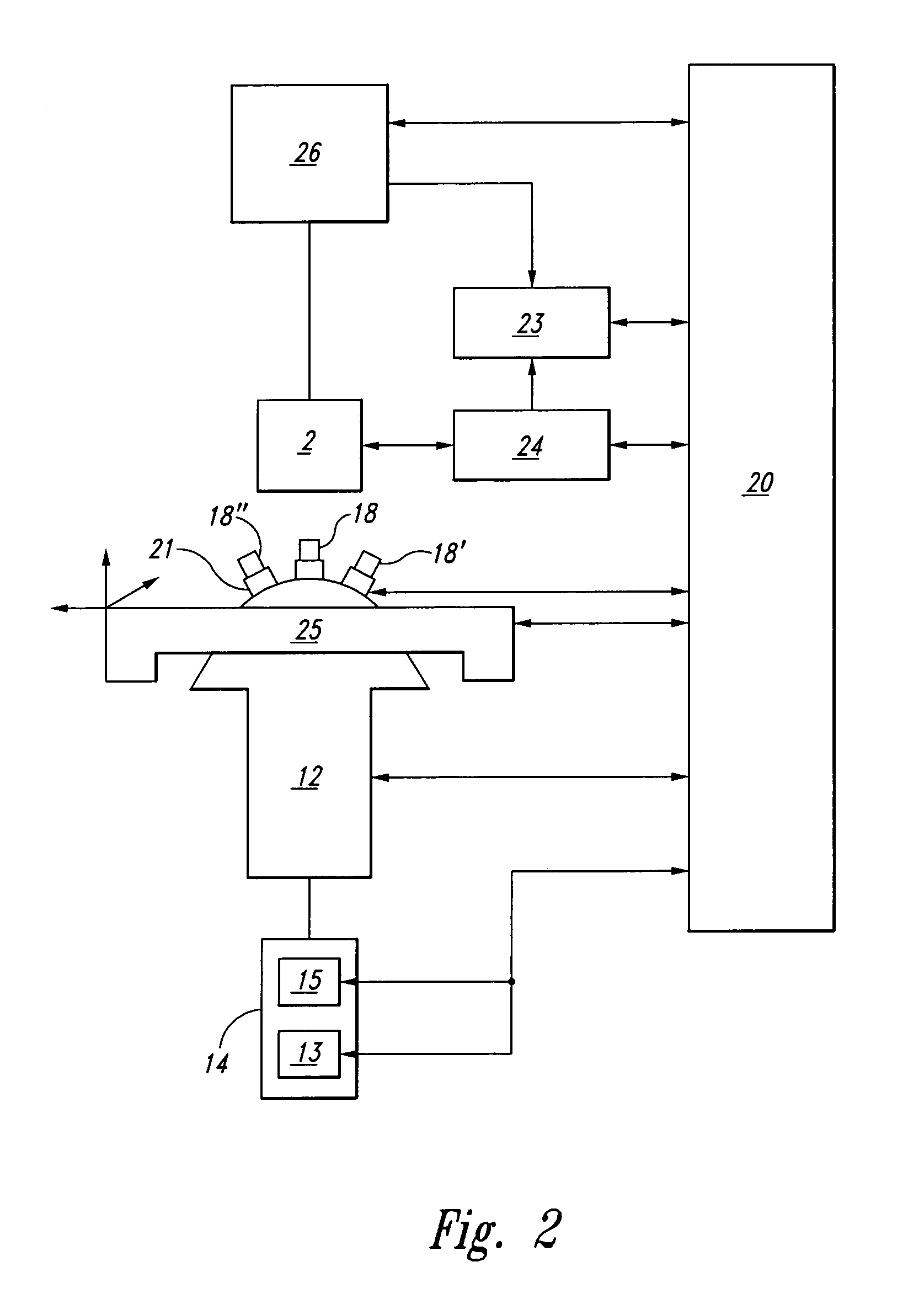
[0023]F...


PUM

PropertyMeasurementUnit
timeaaaaaaaaaa
timeaaaaaaaaaa
timeaaaaaaaaaa

Abstract

A method and apparatus for laser-assisted fault mapping which synchronizes the laser control with the tester unit. The inventive method provides for laser-assisted pseudo-static fault mapping to localize defects in a device whose inputs are being stimulated dynamically by a tester. It further provides for laser-assisted dynamic soft error mapping, to localize in terms of location and to correlate with respect to a specific test vector, sensitive areas in a device by utilizing device performance criteria such as pass-fail status outputs. The apparatus includes a fully controllable dynamic laser stimulation apparatus connected to a control unit that provides complete synchronization with a tester unit.

Description

CROSS-REFERENCE TO RELATED APPLICATIONS[0001]This application claims priority to U.S. Provisional Patent Application No. 60 / 486,490 titled “Spatial and Temporal Selective Laser Assisted Fault Localization,” filed Jul. 11, 2003, which is hereby incorporated by reference herein.FIELD OF THE INVENTION[0002]Aspects of this invention relate to apparatus and methods of localization, identification, and mapping of faults, defects, or sensitive areas in integrated circuit devices, and in particular to the use of a laser synchronized with a tester to achieve such localization, identification, and mapping.BACKGROUND OF THE INVENTION[0003]As integrated circuits become smaller, denser, and faster, development of new methods for testing and debugging has become necessary. In particular, the localization of defects or sensitive areas in circuits, which may contribute to or cause operational failures, is a critical element in debug and failure analysis, as well as enabling circuit repairs with cha...

Claims


Application Information

Patent Timeline
Patent Type & Authority Patents(United States)
IPC IPC(8): G01R31/302G01R31/26G01R31/28G03C5/00G06F17/50H01J37/08G21K5/10G01R31/311H01S
CPCG01R31/311G01R31/31816
Inventor PERDU, PHILIPPEDESPLATS, ROMAINBEAUDOIN, FELIXVEDAGARBHA, PRAVEENLEIBOWITZ, MARTINWILSHER, KENNETH R.
Owner DCG SYST
Why Eureka
Try Eureka