Medical implant and method of reducing back pain

Inactive Publication Date: 2004-03-11
PATEL TUSHAR
View PDF32 Cites 28 Cited by
  • Summary
  • Abstract
  • Description
  • Claims
  • Application Information

AI Technical Summary

Problems solved by technology

Hence, they were not well suited to meet the peculiar requirements of the human spine.
Accordingly, there is a likelihood that the prosthesis would lead to further spinal damage upon loading.
In addition, a Swartz '459 prosthesis with its near circular configuration would have an undesirable amount of mobility within the spine since this type of prosthesis is not well suited for the unusual structures and more complex geometry of the spine.
Un

Method used


Image

  • Medical implant and method of reducing back pain
  • Medical implant and method of reducing back pain
  • Medical implant and method of reducing back pain

Examples


Example

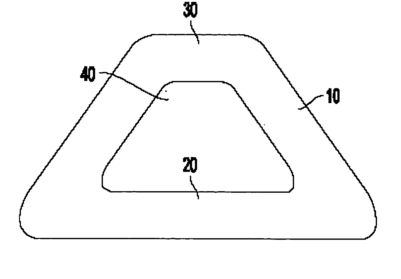
[0012] Accordingly, certain embodiments of the present invention are directed at expandable medical implants (i.e., prostheses) that substantially obviate one or more of the problems due to the limitations and disadvantages of the related art. Certain embodiments of the present invention are also directed at methods of manufacturing medical implants and at methods of reducing back pain that obviate one or more of the limitations and disadvantages of the related art.

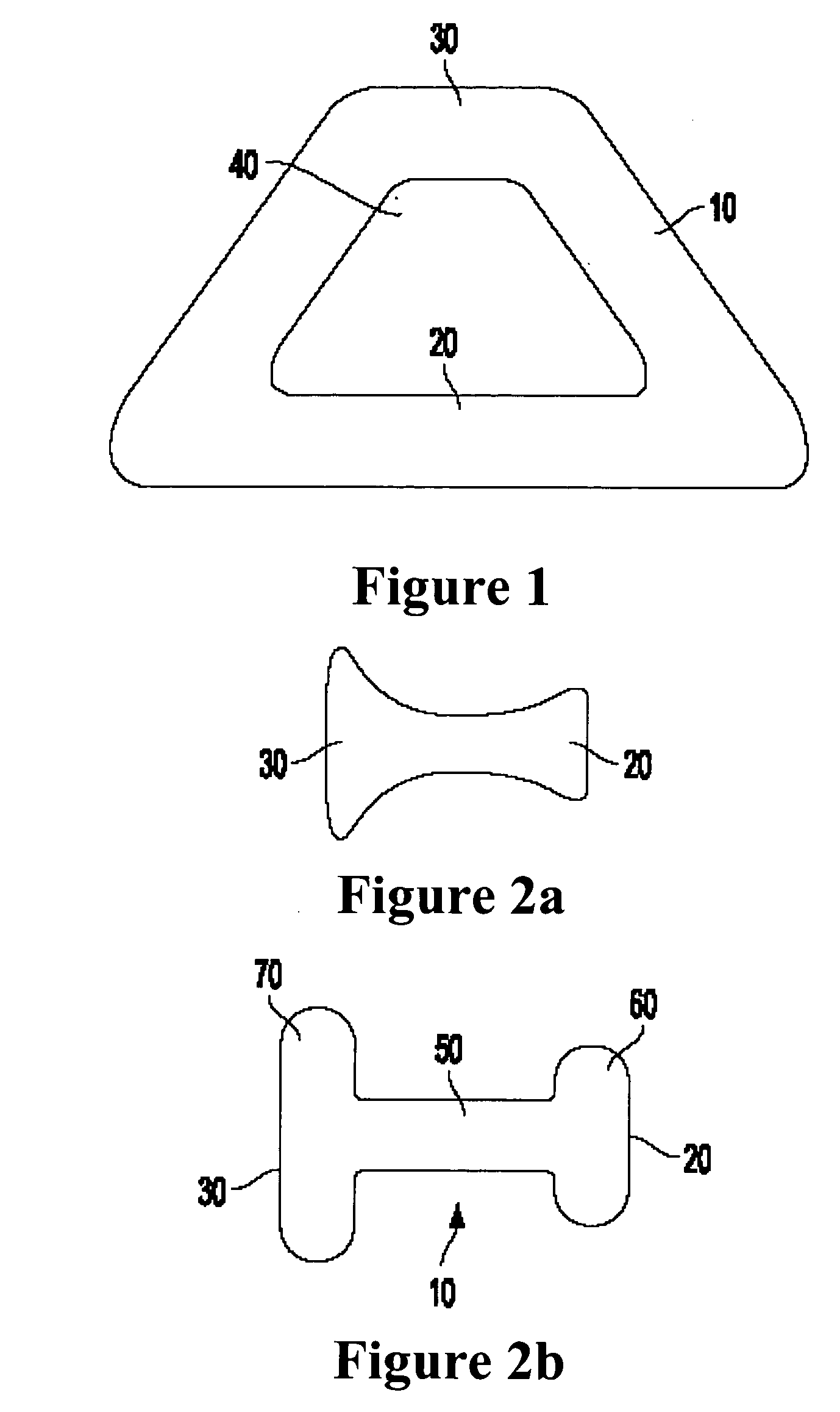
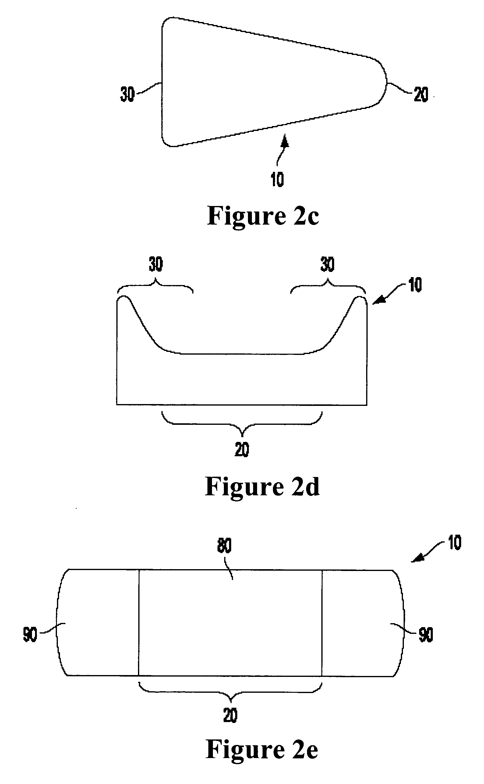
[0013] According to one embodiment of the present invention, a medical implant is provided that includes an expandable cover or shell having an interior portion and a peripheral portion that surrounds the interior portion. The implant is manufactured to have appropriate dimensions for insertion thereof between a first vertebral endplate and a second vertebral endplate. When in an expanded position, the peripheral portion of the implant has a thicker cross-section than the interior portion of the implant.

[0014] According t...


PUM

PropertyMeasurementUnit
Pressureaaaaaaaaaa
Dimensionaaaaaaaaaa
Heightaaaaaaaaaa

Abstract

An expandable medical implant capable of being inserted between adjacent vertebral endplates in a spine. The implant, when in an expanded position, includes a thicker peripheral portion and a thinner interior portion. Also, a method of manufacturing an expandable medical implant having a thicker peripheral portion and a thinner interior portion. Further, a method for reducing back pain that includes placing a medical implant between two adjacent vertebral endplates and positioning the implant such that the implant distributes stresses toward stronger portions of the endplates when pressure is placed on the implant.

Description

[0001] The present application claims priority from U.S. Provisional Patent Application No. 60 / 385,745 (hereafter, "the '745 Application"), which was filed on Jun. 4, 2002 entitled "Nucleus Implant that Prevents Endplate Subsidence". The '745 Application is hereby incorporated herein in its entirety by reference.[0002] 1. Field of the Invention[0003] The field of the present invention includes medical implants, methods of manufacturing the same and methods of reducing back pain.[0004] 2. Description of the Related Art:[0005] A healthy human spine includes a set of vertebrae and a set of discs that are positioned between the vertebrae. Each disc includes two endplates, a gelatinous and relatively soft nucleus, and a fibrous and relatively rigid annulus. The nucleus is located in the center of the disc, the annulus surrounds the nucleus, one of the endplates is positioned above the nucleus and annulus, and the other endplate is positioned below the nucleus and annulus. The endplates a...

Claims


Application Information

Patent Timeline
IPC IPC(8): A61B17/86A61F2/00A61F2/02A61F2/30A61F2/44A61F2/46
CPCA61B17/86A61F2250/0036A61F2/441A61F2/442A61F2002/30014A61F2002/30062A61F2002/30166A61F2002/302A61F2002/30311A61F2002/30324A61F2002/30448A61F2002/30556A61F2002/30579A61F2002/30586A61F2002/30677A61F2002/30948A61F2002/444A61F2002/4631A61F2210/0004A61F2220/005A61F2230/0028A61F2230/0065A61F2250/0009A61F2250/0018A61F2/30767
Inventor PATEL, TUSHAR
Owner PATEL TUSHAR
Why Eureka
Try Eureka