System and Methods for Diagnosis and Treatment of Discogenic Lower Back Pain

a lower back pain and discogenic technology, applied in the field of energy impulse delivery, can solve the problems of disc rupture or bulging outward, sprain, strain, or spasm in one or more muscles or ligaments in the back, and the posterior longitudinal ligament may be injured, so as to prevent the rotation and migration of the leads and reduce back pain

Active Publication Date: 2016-03-10
LIPANI JOHN D
View PDF3 Cites 16 Cited by
  • Summary
  • Abstract
  • Description
  • Claims
  • Application Information

AI Technical Summary

Benefits of technology

[0045]According to the invention, the stimulation in this region may reduce back pain in a patient reversibly, adjustably, and with almost complete coverage of the pain-generating region, for example, by interfering with or modulating afferent pain signals to the brain that originate in those nerves. All stimulating electrodes, light sources, vibrators, heaters or coolers are unidirectional, such that the electrodes or other energy-producing devices are located on one side of the insulating material to which they are attached, e.g., a flexible, inert silicone elastomer (such as Silastic™) or similar flexible material, to prevent stimulation to the overlying thecal sac and the nerves contained therein.
[0047]Because of the potential danger of accidentally stimulating the thecal sac and nerves contained therein, the temporary lead is specially designed to prevent accidental rotation of energy-producing or energy-transmitting devices of the lead towards the thecal sac. The sides of the lead preferably comprise fins that protrude from the main body of the lead which, when inserted into the tissue of the anterior epidural space, will prevent rotation and migration of the leads. Furthermore, although the body of the temporary lead may be shaped in a conventional catheter-like cylindrical form, a flat shape with a rounded or curved tip is preferable in order to prevent rotation and to maintain directionality of electrodes or other energy-transmitting devices of the lead toward the PLL. In order to implant such flat and / or finned leads into a suitable position, special percutaneous implantation methods and devices are used. Intraoperative electrophysiological monitoring is also used to confirm that the thecal sac is not being damaged or stimulated by a lead, either during the lead's insertion or when pulses of energy are applied to the lead.
[0048]If nerve stimulation via the temporary energy-producing devices is successful in reducing back pain, a permanent array of energy-producing devices is implanted and attached by wires to an internal (implanted) pulse generator, or in the case of the transmission of light they may be connected with optical fibers. The permanent energy-producing devices are generally disposed nonlinearly across the surface of a paddle lead (plate lead or surgical lead). The direction and route of permanent electrode insertion may be chosen based on the implanter's preference and the extent of the pain generating region. The objective is for the energy emitted or transmitted by the energy-producing devices to cross the path of nerves identified as the stimulation target. The permanent paddle leads are specially designed to contour the posterior vertebral column, such that the surface area of the contact electrodes narrows in those regions bound by two pedicles. This configuration also aids in anchoring the leads in place. Similar to temporary leads, permanent leads may be placed horizontally along the width of the posterior annulus of an intervertebral disc and overlying PLL or placed longitudinally along the PLL that spans the distance between one or more intervertebral discs. The length and width of the paddle leads will vary to accommodate the corresponding dimensions of the pain-generating region as measured on CT or MRI in individual patients.

Problems solved by technology

The posterior longitudinal ligament may be injured (sprained, as a stretch and / or tear) as the result of sudden violent contraction, sudden torsion, lifting a heavy object, or other acute mechanical events.
Pain may be elicited during times of overexertion that results in sprain, strain, or spasm in one or more of the muscles or ligaments in the back.
If the spine becomes overly strained or compressed, a disc may rupture or bulge outward.
Prolonged stresses or degenerative changes facilitated by genetic predisposition, aging, obesity, smoking, arthritis, poor posture, or unhealthy activity-related habits may result in injury to the intervertebral disc, resulting in chronic discogenic-mediated low back pain [Devon I RUBIN.
It tends to last a month or more or may be a persistent unrelenting problem.
However, interpretation of results given by provocative discography and nerve blockade can be equivocal or controversial, and those methods do not necessarily predict the success of potential disc therapies.
As described in the above-cited publications, all of these techniques have varying degrees of success, and pain relief is generally temporary.
A problem with IDET and similar minimally invasive techniques is that destruction of nociceptors within the posterior annulus is variable and incomplete.
In addition, the offending region involving the PLL is not addressed.
However, as disclosed below, such general-purpose stimulators are not well-suited for the objectives of the present invention.
However, a percutaneous lead may be accidentally introduced into the anterior epidural space, which is considered to be an error, and the lead is withdrawn.
All of these factors contribute to the challenge of being able to direct stimulation selectively to the low back without interference from the body walls.
A Cochrane review of random clinical trials for the treatment of FBSS by spinal cord stimulation concluded that although one clinical trial does provide some limited evidence in favor of spinal cord stimulation, the numbers are small and as a result the study fails to achieve statistical significance [MAILIS_GAGNON A, Furlan A D, Sandoval J A, Taylor R. Spinal cord stimulation for chronic pain.
Such stimulation of the cauda equina would be very undesirable because it would cause leg movements resulting from stimulation of nerve roots within the cauda equina.
In fact, there are only a few reasons for electrically stimulating the cauda equina, and they are not relevant to the treatment of discogenic back pain.
A second problem is that electrodes, particularly percutaneous electrodes (wire, or catheter-like electrodes) have a tendency to migrate or rotate, such that even if the electrode were initially directed to stimulate the posterior longitudinal ligament, it may eventually rotate or migrate, thereby accidentally stimulating other tissues.

Method used


Image

  • System and Methods for Diagnosis and Treatment of Discogenic Lower Back Pain
  • System and Methods for Diagnosis and Treatment of Discogenic Lower Back Pain
  • System and Methods for Diagnosis and Treatment of Discogenic Lower Back Pain

Examples


Embodiment Construction

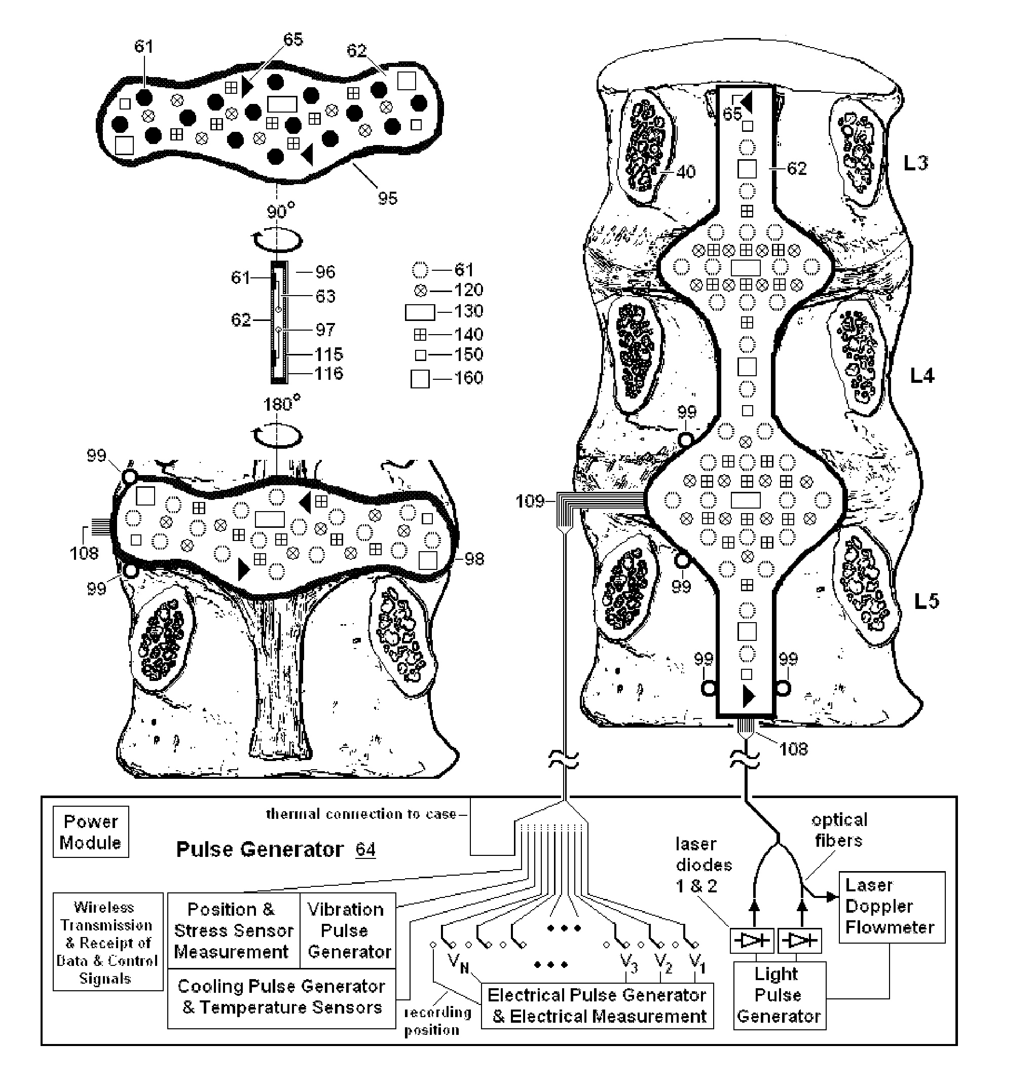
[0065]FIG. 5 shows an array of electrodes and a pulse generator that may be used to stimulate nerves in the posterior longitudinal ligament and underlying annulus fibrosus, according to the present invention. An array of electrodes is also known as a lead. In FIG. 5A, the lead 60 is shown to be a percutaneous flat lead. The width of the lead may be, for example, 0.5 cm. As shown, it contains eight contact electrodes 61, which are embedded in insulating material 62. For example, the contact electrodes may be made of an alloy of platinum / iridium, and the insulation material may be made of a flexible, inert silicone elastomer (such as Silastic™), polyurethane or silicone / polyurethane. When the lead is rotated by 90 degrees and sectioned along its axis, wires 63 are seen to connect each contact to corresponding connection points in the Pulse Generator 64. The wires 63 may also be embedded in the insulating material 62. For example, the wires may be made of the conducting material 35NLT-...


PUM


Abstract

Methods and devices to treat discogenic lumbar back pain are disclosed. Electrodes are implanted within the anterior epidural space of the patient. A pulse generator that is connected to the electrodes delivers electrical impulses to sympathetic nerves located within the posterior longitudinal ligament (PLL) of the lumbar spine and outer posterior annulus fibrosus of the intervertebral disc. In alternate embodiments, energy directed to nerves in the PLL may be from light or mechanical vibrations, or the nerves may be cooled. The electrodes may also be used diagnostically to correlate spontaneous nerve activity with spinal movement, fluctuations in autonomic tone and the patient's experience of pain. The electrodes may also be used to generate diagnostic evoked potentials. The diagnostic data are used to devise parameters for the therapeutic nerve stimulation. Automatic analysis of the data may be incorporated into a closed-loop system that performs the nerve stimulation automatically.

Description

CROSS REFERENCE TO RELATED APPLICATIONS[0001]The present application is a division of pending U.S. application Ser. No. 14 / 465,822 having publication No. US 20150005680, which was filed on Aug. 21, 2014. That pending application is a continuation-in-part of application Serial Number U.S. Ser. No. 13 / 402,093 having publication No. US 20120215218, which was filed Feb. 22, 2012 and which issued as U.S. Pat. No. 8,880,189 on Nov. 4, 2014. The present application also claims the benefit of a division of that application Serial Number U.S. Ser. No. 13 / 402,093, namely, Serial Number U.S. Ser. No. 14 / 099,910 having publication No. US 20140135876, which was filed 7 Dec. 2013 and which issued as U.S. Pat. No. 8,892,215 on Nov. 18, 2014. Those three applications, as well as the present application, claim the benefit of provisional patent application number U.S. 61 / 463,800, entitled System and Method for Electrical Stimulation of the Lumbar Vertebral Column, to J. D. LIPANI, with a filing date ...

Claims


Application Information

Patent Timeline
Patent Type & Authority Applications(United States)
IPC IPC(8): A61N1/36A61N1/372A61N1/05A61B18/14A61B18/20
CPCA61N1/36071A61B18/1492A61B18/20A61N1/0558A61N1/37205A61N1/37223A61B2018/00434A61B2017/320069A61B2018/00047A61B2018/00577A61B2018/00613A61B2018/00815A61B2018/00821A61B2018/1807A61N1/0551A61N1/36057A61N1/3614A61N1/36146A61N1/36167A61N1/36171A61N1/36178A61N1/37211A61F7/12A61H23/02A61H2205/081A61N5/0622
Inventor LIPANI, JOHN D.
Owner LIPANI JOHN D
Why Eureka
Try Eureka