Supine spinal column flexing fixture and method

a spinal column and fixture technology, applied in the field of spinal column flexing fixtures, can solve the problems of ineffectiveness, discourage continued use, and contribute to pain and lack of articulation, so as to reduce the build-up of calcium deposits surrounding the vertebrae, increase the separation of spinal vertebrae, and reduce the build-up of calcium deposits

Inactive Publication Date: 2000-06-06
RIVERA ARNOLD
View PDF3 Cites 20 Cited by
  • Summary
  • Abstract
  • Description
  • Claims
  • Application Information

AI Technical Summary

Benefits of technology

It is an additional objective of this invention to provide a device and method for increasing separation of the spinal vertebrae.
It is likewise an objective of this invention to provide a device and method to reduce the build up of calcium deposits surrounding the vertebrae.
It is a further objective of this invention to provide a device and method which can soften the nucleus pulposus and anulus fibrosus.
It is an additional objective of this invention to provide a device and method which will enhance blood flow to spinal column areas, thereby increasing the delivery of oxygen, nutrition and enzymes to those areas.
It is yet another objective of this invention to provide a device and method that will relieve back pain and discomfort.
It is a further objective of this invention to provide a device which is simple to use and a method which requires only a few minutes of activity each day.

Problems solved by technology

With injury, aging and lack of exercise, the nucleus pulposus hardens and the vertebrae lose freedom of articulation, resulting in a latent condition in which even minor activity can result in irritation and inflammation that applies pressure to the nerves, causing pain.
In some injuries, the nucleus extrudes; a condition known as a herniated disk, which greatly contributes to pain and lack of articulation.
This method has the commendable goal of forced articulation of the vertebrae, however, the rollers which have been suggested for this purpose typically have an overly aggressive design which can cause discomfort, injuries or bruises that discourage continued usage.
Most of these patented devices also have raised circular rims on each side of the central groove and are not particularly effective as they do not place stress on the spinal column, but rather apply uncomfortable, and potentially bruising forces to one's back tissue and muscles.
The size of the central ball, and the lack of lateral support by the smaller diameter balls renders this device overly aggressive and its use by inexperienced patients can result in injury or accentuate back pain.
A common failing of all these devices is the aggressiveness of treatment, either by failure to provide support across one's entire back, which unavoidably concentrates forces at localized areas with consequential discomfort and the potential of injury.

Method used


Image

  • Supine spinal column flexing fixture and method
  • Supine spinal column flexing fixture and method
  • Supine spinal column flexing fixture and method

Examples


Embodiment Construction

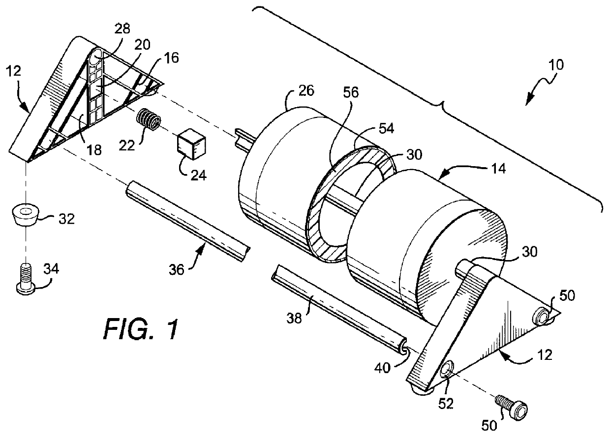
FIG. 1 is an exploded perspective view of the roller fixture 10 of the invention which, preferably, is used to practice the treatment of the invention. FIGS. 2-4 are top, front and end views of the assembled roller fixture 10. As there illustrated, the fixture 10 comprises a pair of end brackets 12 at each end of a long cylindrical roller 14, which is formed of a plastic cylinder with permanently attached end caps which support the roller shaft. In the illustrated embodiment, the brackets 12 are triangular end plates molded of a suitably strong plastic. Each bracket 12 is hollowform with internal webbing or bracing 16 and has an internal post 18 which has a recess 20 that receives a compression spring 22 and a plastic block 24 which serves as a friction brake as it is pressed against the end cap 26 of the roller 14 by the resilient bias of the spring 22.

At its upper end, the post 18 has a cylindrical recess 28 to receive the end of the roller shaft 30, thereby providing rotational s...


PUM


Abstract

There is disclosed a therapeutic exercise in which the patient lies in a supine position on a flat surface, with a long, smooth cylindrical roller having a constant compressed diameter from about 2 to about 4 inches throughout its length beneath the patient's back. The roller should be of sufficient length to span laterally across the entire patient's back and shoulders. The patient's slowly rolls his body over the roller from the sacrum along the lumbar and thoracic vertebrae by the pushing against the support surface with his feet and hands, and while shifting or rocking his body, side-to-side. The roller fixture includes a pair of end brackets which rotationally support a pair of end shafts of the roller and includes a frictional brake to restrain the rotation of the roller.

Description

1. Field of InventionThis invention relates to a method and apparatus for flexing of the spinal column and, in particular, to a device and method for its use in therapy and exercise.2. Brief Statement of the Prior ArtChronic back pain is an affliction that affects most persons during their lifetime. It is caused by many factors, principally traumatic injuries from falls or bodily contact sports, and is fostered by a sedentary lifestyle. The spinal column is formed with a plurality of articulated vertebrae which surround the spinal nerves and which separated by intervertebral disks having a central gelatinous body (nucleus pulposus) surrounded by annular layers of collagen fibris (anulus fibrosus). The nucleus cushions or absorbs shocks and weight applied to the spinal column. With injury, aging and lack of exercise, the nucleus pulposus hardens and the vertebrae lose freedom of articulation, resulting in a latent condition in which even minor activity can result in irritation and in...

Claims


Application Information

Patent Timeline
Patent Type & Authority Patents(United States)
IPC IPC(8): A61H15/00A61H1/02
CPCA61H1/0292A61H15/00A61H2205/081A61H2015/0014
Inventor RIVERA, ARNOLD
Owner RIVERA ARNOLD
Why Eureka
Try Eureka