Mixed screen design for multi-mode document

Inactive Publication Date: 2004-03-18
SEIKO EPSON CORP
View PDF8 Cites 13 Cited by
  • Summary
  • Abstract
  • Description
  • Claims
  • Application Information

AI Technical Summary

Benefits of technology

0007] It is an object of the present invention to depict smoothly a plurality of gray levels using different halftone screens and halftone patterns by combining elements of a first halftone pa

Problems solved by technology

Halftoning techniques address certain limitations of binary printing devices, which operate by turning a pixel "on" or "off" without the capability of depicting intermediate intensity or "gray" levels.
The use of different halftone patterns, or the use of multiple halftone screens of different sizes within a halftoned image can cause some printing devices to produce defects in regions of the printed image where more than one halftone screen or pattern are used.
Some defects are printer-dependent and in many cases their appearance is unpredictable.
Common techniques that apply different halftone patterns having the same screen frequency to render multiple gray levels generally produce a smooth transition in gray level from darker to lighter regions; however, in some printing devices a defect known as a "discontinuity" may appear in which an abrupt change from one gray level to another is visible within the transition region.
If the high-frequency and l

Method used


Image

  • Mixed screen design for multi-mode document
  • Mixed screen design for multi-mode document
  • Mixed screen design for multi-mode document

Examples


Embodiment Construction

System Overview

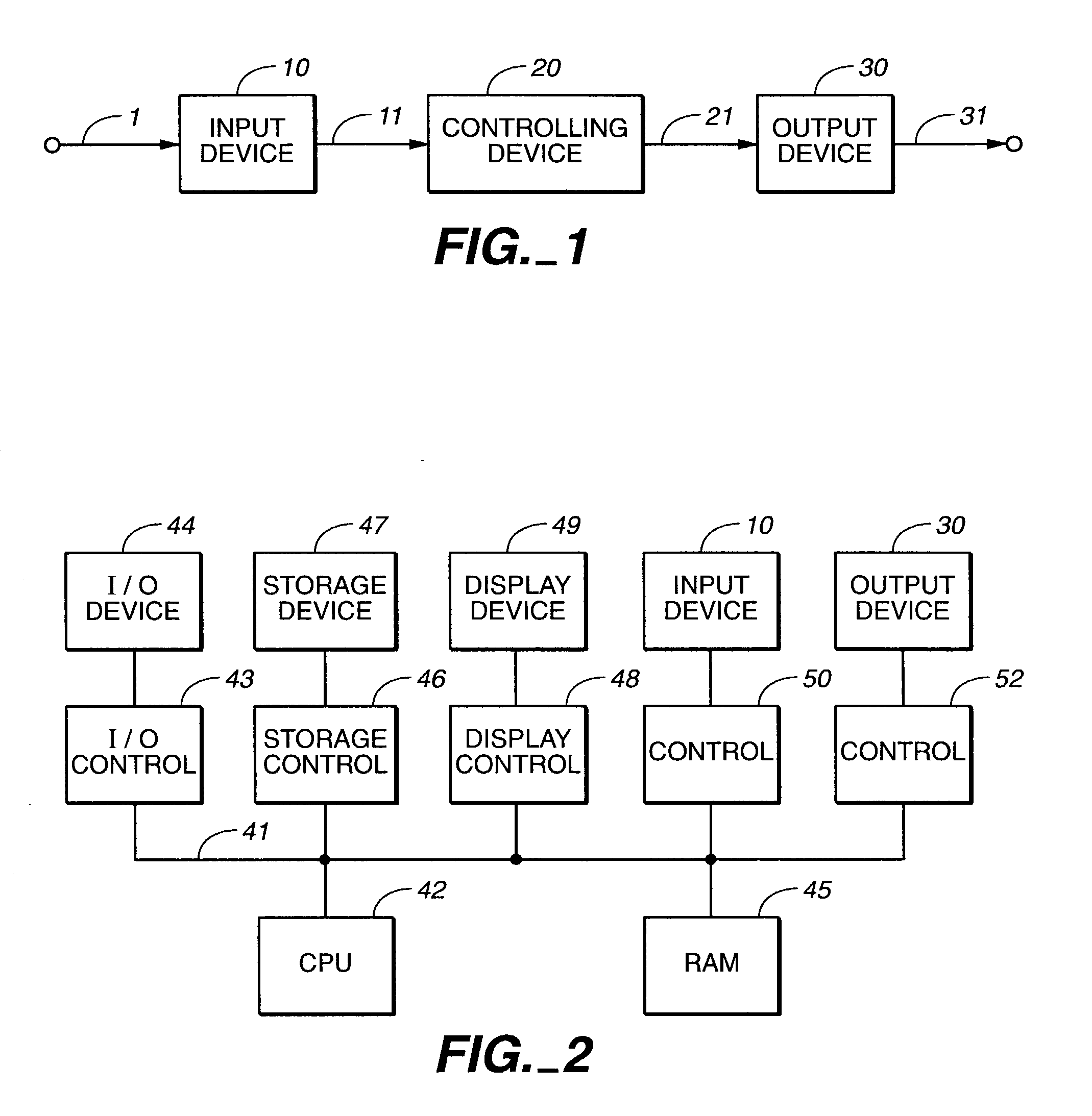
[0023] FIG. 1 illustrates major components in a typical image reproduction system. Input device 10 receives from path 1 signals representing an original image and generates along path 11 a rasterized representation of the original image. Controlling device 20 receives this representation from path 11 and, in response, generates along path 21 an output-device-dependent representation of the original image. Output device 30 receives this representation from path 21 and, in response, generates along path 31 a printed representation of the original image. The present invention is directed toward improving the perceived quality of the printed representation produced by the output device.

[0024] Input device 10 may be a software application capable of generating text or graphics images or image data representing a photographic image. Alternatively, input device 10 may be an apparatus such as a scanner or camera. If input device 10 is a software application for creating image...


PUM


Abstract

A superpattern generator uses a first halftone pattern representing a first gray level and a second halftone pattern representing a second gray level to generate a larger pattern or "superpattern". In a preferred implementation, the superpattern generator generates a grid of elements to be used as a template for the superpattern, calculates a distance value representing the "distance" from the first gray level to a desired gray level TX, determines how many elements of the grid represent the first halftone pattern and how many represent the second halftone pattern based on the distance value, superimposes a dither matrix on the grid and assigns values representing the first halftone pattern or the second halftone pattern to pixels within the elements of the grid by examining threshold values in the dither matrix. This process is repeated for various values of TX to generate a set of superpatterns representing a set of gray levels intermediate to the first gray level and the second gray level.

Description

[0001] The invention relates to the processing of image data for the purpose of enhancing the appearance of an image as presented by a device such as a printer or display.[0002] Halftoning is a technique commonly used to convert a rasterized image into an output image. Halftoning techniques address certain limitations of binary printing devices, which operate by turning a pixel "on" or "off" without the capability of depicting intermediate intensity or "gray" levels. Halftoning techniques make it possible for such devices to depict multiple gray levels by representing features in a printed image using patterns of small dots. If the human eye views a pattern of sufficiently small dots, the viewer generally does not perceive the individual dots but instead perceives the average gray level of the pattern. Halftoning techniques accordingly depict different regions within an image by using different patterns of small dots chosen to have an appropriate average gray level. A binary printin...

Claims


Application Information

Patent Timeline
IPC IPC(8): H04N1/405
CPCH04N1/4057
Inventor HUANG, JINCHENGSHU, JOSEPH
Owner SEIKO EPSON CORP
Why Eureka
Try Eureka