Stent delivery system and method

a stent and delivery system technology, applied in the field of ureteral stents, can solve problems such as problems such as troublesome deploymen

Inactive Publication Date: 2004-04-15
APPL MEDICAL RESOURCES CORP
View PDF6 Cites 22 Cited by
  • Summary
  • Abstract
  • Description
  • Claims
  • Application Information

AI Technical Summary

Problems solved by technology

Since stents are formed at a predetermined length, namely, to extend between the kidney and the bladder, deployment is problematic especially when there remains no further portion of the stent external to the urethra to be advanced.

Method used


Image

  • Stent delivery system and method
  • Stent delivery system and method
  • Stent delivery system and method

Examples


Embodiment Construction

[0047] The invention and its various embodiments can now be better understood with the following detailed description wherein illustrated embodiments are described. It is to be expressly understood that the illustrated embodiments are set forth as examples and not by way of limitations on the invention which is ultimately defined in the claims.

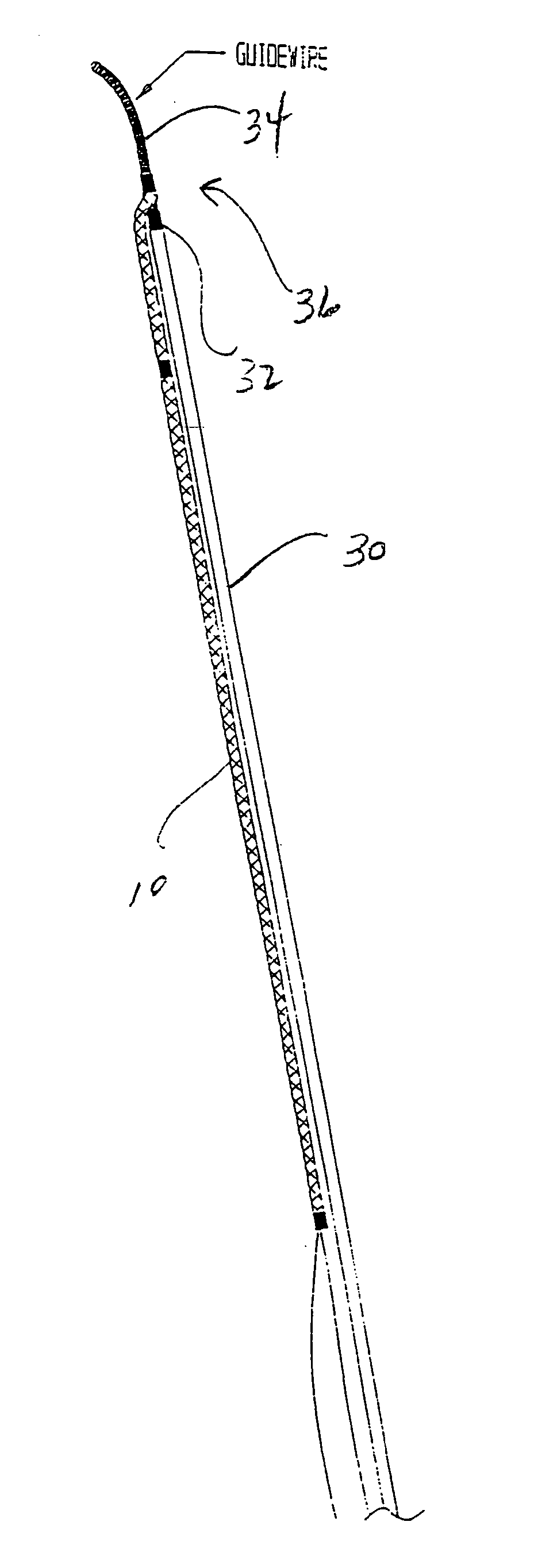
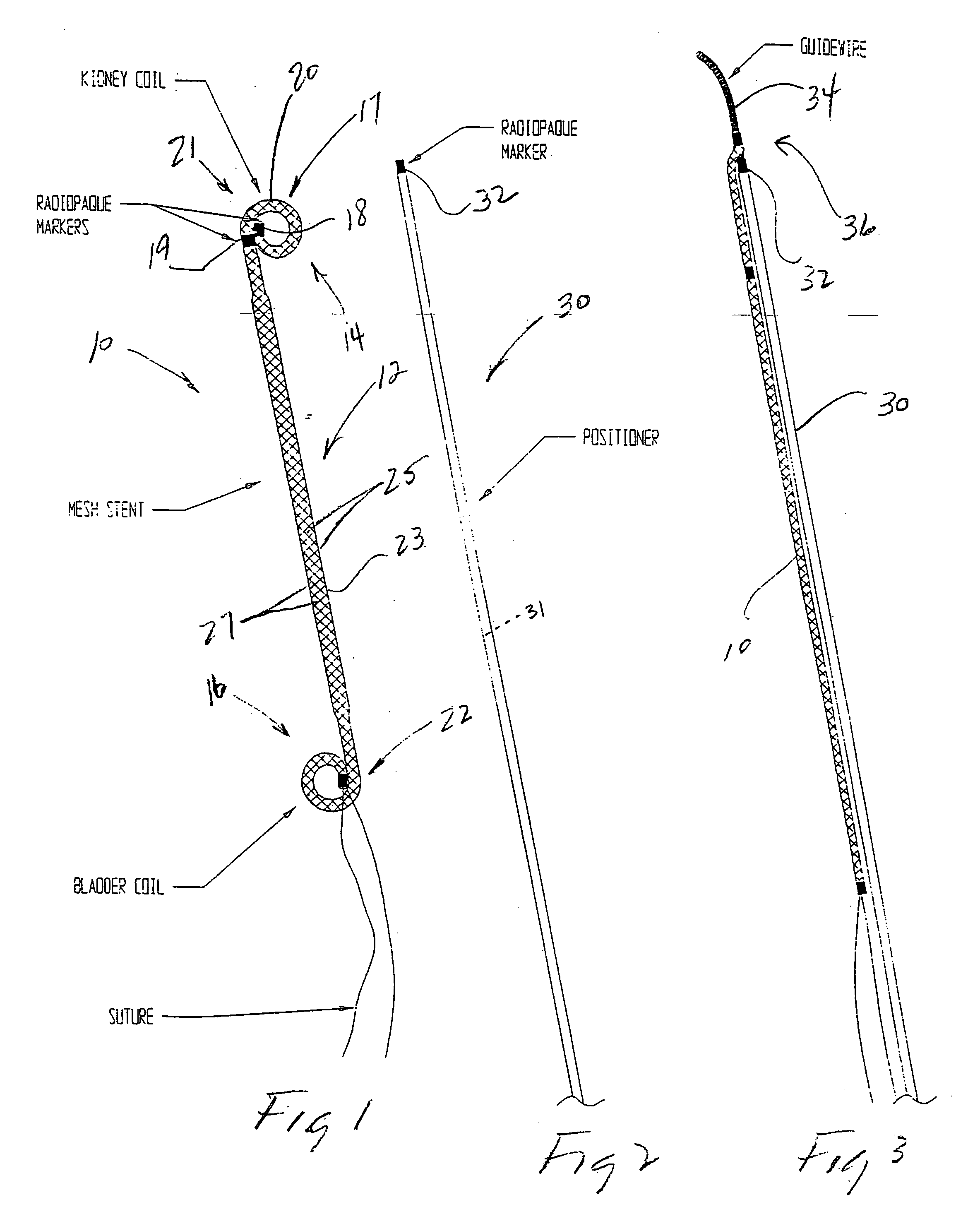
[0048] A ureteral stent is illustrated in FIG. 1 and designated by the reference numeral 10. The stent 10 has an elongate configuration defined by a body 12 extending between a distal end 14 and proximal end 16. A distal section 17 and proximal section 22 of the stent 10 are of particular interest to the present invention. This section 17 includes radiopaque markers, or sleeves, 18 and 19, and a distal portion 20 of the body 12 which extends therebetween. The marker 18 is disposed at the distal end 14 and may function as a guide bushing. The marker 19 is disposed proximally of the marker 18 and may have a tubular configuration so that it can a...


PUM


Abstract

A braided stent includes coiled distal and proximal anchors adapted to be disposed in the kidney and bladder, respectively. The stent is threaded onto an elongate member which is advanced distally to position the stent through the ureter. The stent may be releasably coupled to a guidewire and advanced distally by a tubular positioner threaded over the guidewire. Retracting the guidewire into the positioner releases the stent and completes deployment. The stent may include a distal nosepiece which may be inserted through a side port and into a first lumen of a dual lumen tube. A rod in the first lumen is advanced forward to engage the nosepiece and thus move the stent distally. Retraction of the rod disengages the stent and thus completes deployment. A second lumen in the tube receives a guidewire which may be moved independently of the rod and stent.

Description

[0001] This application relates to and claims priority from U.S. Provisional Application Serial No. 60 / 258,196 entitled STENT DELIVERY SYSTEM AND METHOD, and filed on Dec. 22, 2000, which is incorporated herein by reference. This application further relates to and claims priority from U.S. Provisional Application Serial No. 60 / 260,833 entitled PARALLEL STENT APPARATUS AND METHOD, and filed on Jan. 9, 2001, which is incorporated herein by reference.[0002] 1. Field of the Invention[0003] The present invention relates generally to medical and surgical devices, and more specifically to ureteral stents and the deployment thereof.[0004] 2. Description of Prior Art and Related Information[0005] Stents are deployed in the ureter to provide fluid communication between the kidney and the bladder. A conventional ureteral stent usually consists of a cylindrical body defining a lumen therein. The conventional stent consists of a single pigtail anchor located at the distal end. A distal tip of th...

Claims


Application Information

Patent Timeline
Patent Type & Authority Applications(United States)
IPC IPC(8): A61F2/00A61F2/90A61M25/00
CPCA61F2/90A61F2002/9505A61M27/008A61F2250/0098A61F2002/9511
Inventor EWERS, RICHARD C.
Owner APPL MEDICAL RESOURCES CORP
Why Eureka
Try Eureka