Eureka AIR delivers breakthrough ideas for toughest innovation challenges, trusted by R&D personnel around the world.

Complex braided scaffolds for improved tissue regeneration

a complex braided scaffold and tissue technology, applied in the field of implantable medical devices and prostheses, can solve the problems of insufficient graft material for extensive or additional repair, inability to adapt to the needs of patients, so as to prevent stress shielding and encourage the regeneration of functional tissu

Pending Publication Date: 2020-10-01
BIOREZ INC
View PDF2 Cites 6 Cited by
  • Summary
  • Abstract
  • Description
  • Claims
  • Application Information

AI Technical Summary

Benefits of technology

[0024]In some embodiments, at least a part of the device is embedded in a foam or sponge. In other embodiments, the entire device is embedded in a foam or sponge. The scaffolds of the devices present a support surface for attachment and ingrowth of tissue cells. The fiber organization of the scaffolds using combinations of fiber sizes and types offers control for each fiber type having a unique and defined purpose. For example, fast resorbing multifilament fibers with small filament diameters have increased surface area to volume ratio to maximize the number of cells attaching to the scaffold and accelerating the reconstruction and regeneration process, while slower resorbing fibers or yarns can provide longer structural integrity. Additionally, 3-D braiding allows certain fibers to be placed strategically in the corners of the structure, or the edge / face of the structure, or in the center of the structure, or in many combinations to control the key properties and characteristics of the device, such as the device shape and mechanical properties throughout the resorption profile. Placing various fiber types such as composite yarns or monofilaments on some or all carriers, or in some or all centers, enables control of the mechanical properties, particularly the stiffness of the structure if the individual fiber / yarn tensions are monitored and controlled.
[0025]The devices are at least partially biodegradable. Typically, the time course for biodegradation of the devices, or portions of the devices, is matched with the time course of regeneration of the tissue being reconstructed. It is the complex three-dimensional braided structure of the scaffold, which enables use of multiple types of fibers, such as fibers differing in composition or size, that allows control over the degradation profile of the device. The degradation profile includes changes in one or more of mechanical strength, elongation, elastic modulus. The device facilitates tissue regeneration throughout the degradation period.
[0026]The degradation of the device occurs in three phases during the regeneration of new tissue. In the first phase, or support phase, the graft contributes most of the structural support of the structure, allowing cells to infiltrate, proliferate, and propagate throughout the open porous scaffold. The elastic nature and relative low stiffness of the device creates mechanobiologic influences on the cells that facilitate the creation of extracellular matrix proteins and tissue. In the second phase, or transition phase, the graft reduces significantly in ultimate strength, transferring and increasing the load onto the developing functional tissue. In the third and final phase, or the degradation phase, the biodegradable scaffold loses all strength, and the new tissue bears all the mechanical loading of the structure. As polymer resorbs in mass and volume, the tissue remodels into mature tissue, reclaiming the space vacated by resorbing polymer.

Problems solved by technology

However, each strategy suffers from a number of limitations.
For example, the benefits of autografts are counterbalanced by function loss and pain at the donor sites, scar tissue formation, structural differences between donor and recipient grafts preventing successful regeneration, and the shortage of graft material for extensive or additional repair.
The use of allograft tissues obviates autograft donor-site complications, but can result in higher rates of failure, such as in younger and more active patients undergoing ACL reconstruction (Wassertein, Sports Health; 7(3):207-216 (2015)).
They are also often associated with issues such as poor integration with surrounding tissue and infection (Dale et al, Acta Orthop 83:449-458 (2012)).
However, tailoring repair and regeneration scaffolds to provide the mechanical properties of orthopedic tissues, especially in the case where the material is biodegradable and ultimately replaced by endogenous cells has been difficult.
These grafts exhibited good short term results but encountered clinical difficulties in long term studies.
Limitations of these synthetic ligament grafts include long term laxity of the replacement material, weakened mechanical strength compared to the original structure and fragmentation of the replacement material due to wear.
The United States Food and Drug Administration (FDA) does not approve or no longer approves these devices for sale, and there are no synthetic graft options currently available for anterior cruciate ligament reconstruction.

Method used


Image

  • Complex braided scaffolds for improved tissue regeneration
  • Complex braided scaffolds for improved tissue regeneration
  • Complex braided scaffolds for improved tissue regeneration

Examples


example 1

hree-Dimensional Braided Scaffolds Formed with Various Braiding Designs

[0242]Materials and Methods

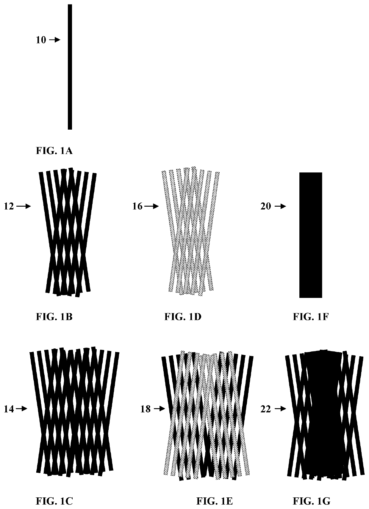
[0243]A four-track three-dimensional braiding technique was used to generate the tissue reconstruction devices. The yarns used in the carriers are monofilament fibers, multifilament yarns, composite multifilament yarns, composite yarns, or combinations thereof. See FIGS. 1A-1G.

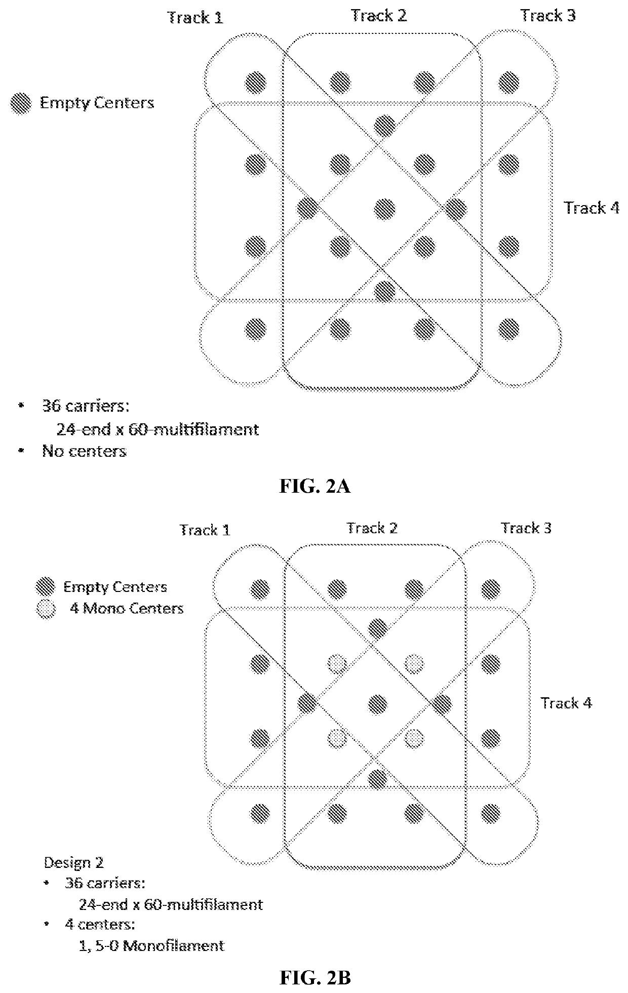
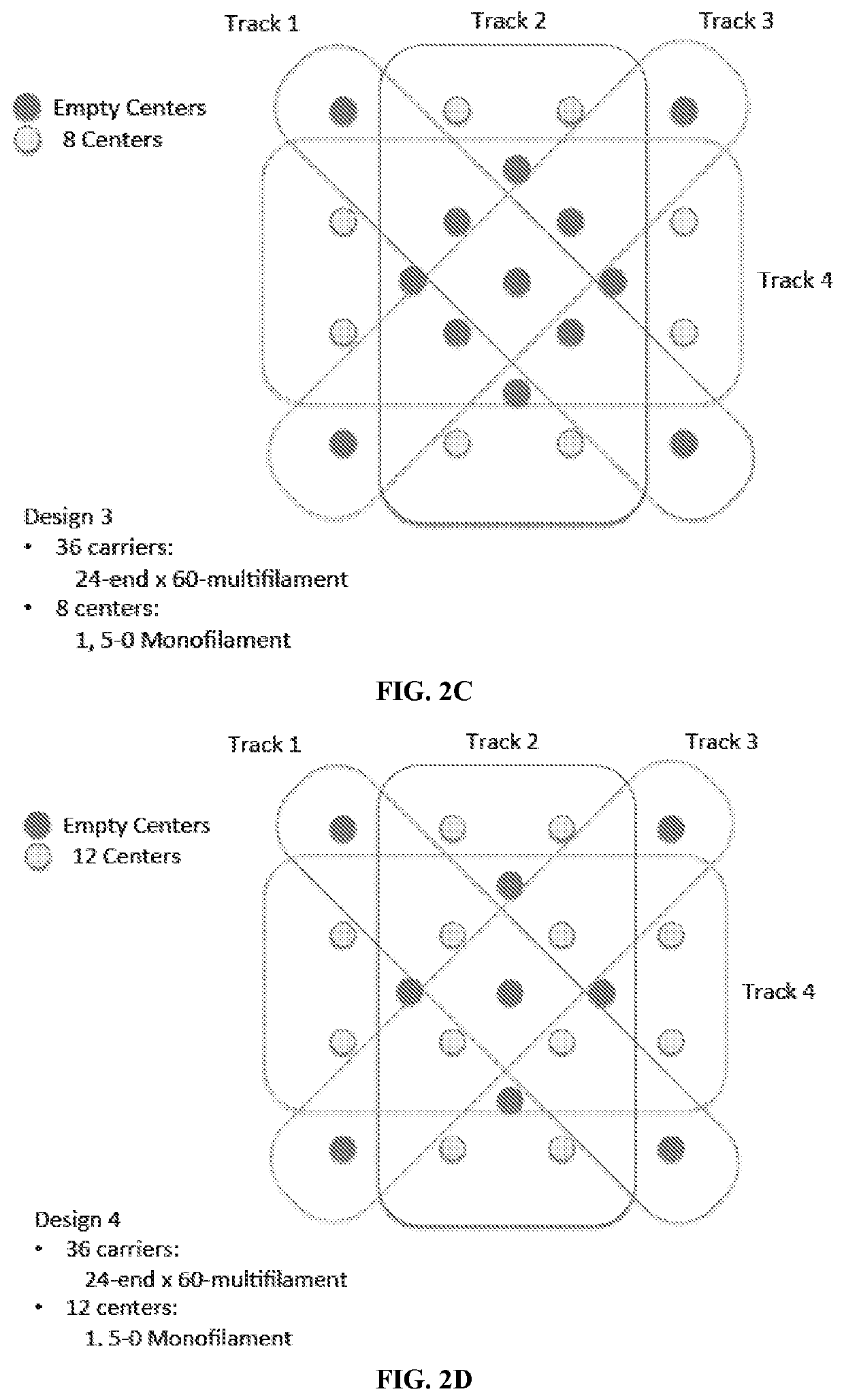
[0244]Sixty (60) such filaments were twisted together to form one multifilament fiber, and 24 such multifilament fibers were twisted together to form one multifilament yarn (24-end×60 multifilament). Composite yarns used were multifilament fibers and monofilament fibers twisted together. Here 40 PLLA filaments each with 15 micron in diameter and one monofilament fiber were twisted around each other to form the composite yarns (mono / multi composite).

[0245]Results

[0246]The designs for yarn arrangement in the three-dimensional braider are presented in FIGS. 2A-2Q. The designs include monofilament-only designs for thr...

example 2

l Properties of Complex Three-Dimensional Braids

[0247]Materials and Methods

[0248]Two different complex braids, designated ‘D3’ and ‘D5’ were constructed.

[0249]D3 was made with 100% twisted P4HB multifilament yarns on all braider bobbins, with twisted PGA multifilament fibers and P4HB monofilament fiber bundles brought into the braid via 17 different center locations.

[0250]D5 was made with 56% of braider bobbins containing twisted P4HB multifilament and monofilament fiber bundles, 44% of braider bobbins containing only P4HB multifilament fiber, and PGA multifilament fiber bundles brought into braid via 17 center locations.

[0251]These devices were then mechanically tested at time zero, and following incubation in PBS over 1 year.

[0252]Results

[0253]D3 and D5 have similar chemical composition but differ in architecture, creating significant differences in mechanical properties.

[0254]After 4 weeks, devices containing PGA have reduced stiffness, indicating a 2 stage resorption profile as ...


PUM

PropertyMeasurementUnit
diameteraaaaaaaaaa
diameteraaaaaaaaaa
diametersaaaaaaaaaa

Abstract

Implantable medical devices and prosthesis for rapid regeneration and replacement of tissues, and methods of making and using the devices, are described. The medical devices include a complex three-dimensional braided scaffold with a polymer composition and structure tailored to desired degradation profiles and mechanical properties. The composite three-dimensional braided scaffolds are braided from yarn bundles of biodegradable and bioresorbable polymeric fibers and / or filaments. Monofilament fibers and / or multifilament fibers can be twisted / plied in different combinations to form multifilament yarns, composite multifilament yarns, or composite yarns. The medical devices are useful as both structural prosthetics taking on the function of the tissue as it regenerates and as in vivo scaffolds for cell attachment and ingrowth.

Description

CROSS-REFERENCE TO RELATED APPLICATIONS[0001]This application claims priority to U.S. Provisional Application No. 62 / 313,246 filed Mar. 25, 2016, which is hereby incorporated herein by reference in its entirety.FIELD OF THE INVENTION[0002]The present invention is in the field of implantable medical devices and prosthesis for rapid reconstruction, regeneration and replacement of tissue, including soft tissue, ligaments and tendons, with a complex braided structure tailored to produce desired mechanical properties and degradation profiles.BACKGROUND OF THE INVENTION[0003]Injuries frequently occur in the musculoskeletal system, accounting for 60-67% of all unintentional injuries in the USA per annum (Ma et al., Nanomedicine, 8(9): 1459-1481 (2013)). It has been reported that more than 34 million musculoskeletal-related surgeries are performed each year in the USA (Deng et al, Trans Nanobiosci, 11L3-14 (2012)). Clinically, the main options available for the surgical treatment of musculo...

Claims


Application Information

Patent Timeline
Patent Type & Authority Applications(United States)
IPC IPC(8): A61F2/08A61L27/56A61L27/18A61L27/50A61L27/54A61F2/00A61L27/14A61L27/58
CPCA61F2250/0023A61L27/56A61F2250/003A61L27/50A61L2300/64A61F2/08A61L27/58A61L27/18A61L2430/10A61L27/54A61F2/0077A61L27/14C08L67/04
Inventor ROCCO, KEVIN A.PETERSON, DALE R.REILLY, JOSEPH W.
Owner BIOREZ INC
Why Eureka
Eureka Blog
Learn More