Method for particle production

Inactive Publication Date: 2005-06-30
CLEARY MICHAEL
View PDF20 Cites 5 Cited by
  • Summary
  • Abstract
  • Description
  • Claims
  • Application Information

AI Technical Summary

Benefits of technology

[0012] d) the use of a double adhesive layer that allows removal of the micro particles from the support i

Problems solved by technology

This results in the particles being excessively large due to the inclusion of irrelevant information.
The prior art

Method used


Image

  • Method for particle production
  • Method for particle production
  • Method for particle production

Examples


Embodiment Construction

[0039] The present invention will be described further, by way of several non-limiting examples of a method of producing a batch of micro particles in accordance with the invention.

[0040] A sheet of suitable substrate typically 30 cm by 30 cm, such as a plastic / metal laminate with the metal layer applied via vacuum deposition or a plastic sheet, is adhered to a flat and inert support, preferably a flat sheet of glass by means of a suitable adhesive. A spray adhesive such as 3M Spray Mount Adhesive has been found to be particularly suitable.

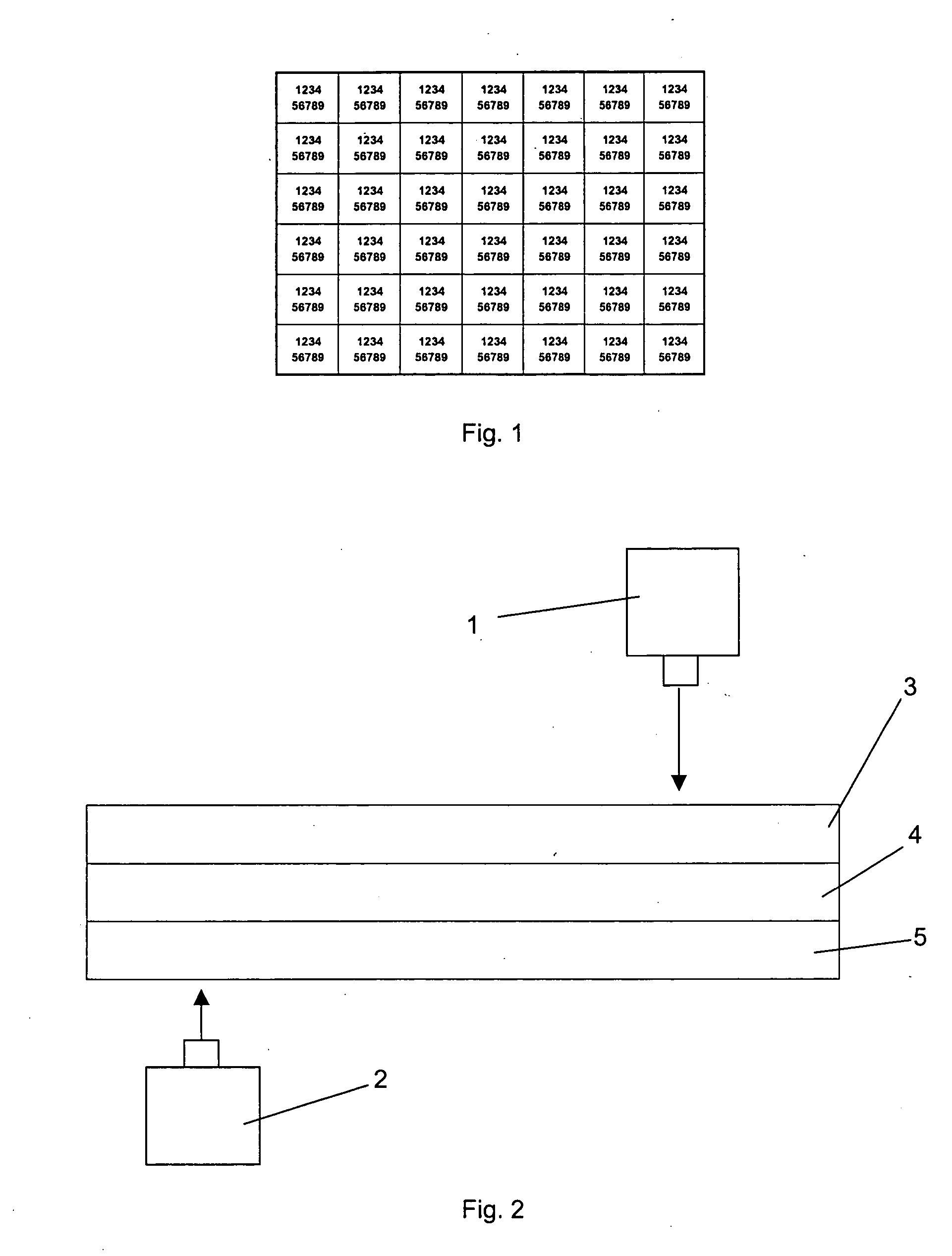
[0041] The support, along with the substrate adhered thereto, is mounted on a stage movable in a plane perpendicular to a laser system. Movement of the stage in x-y coordinates is controlled by a computer.

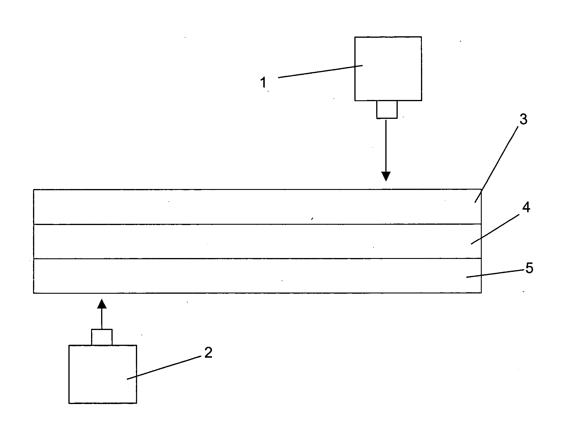
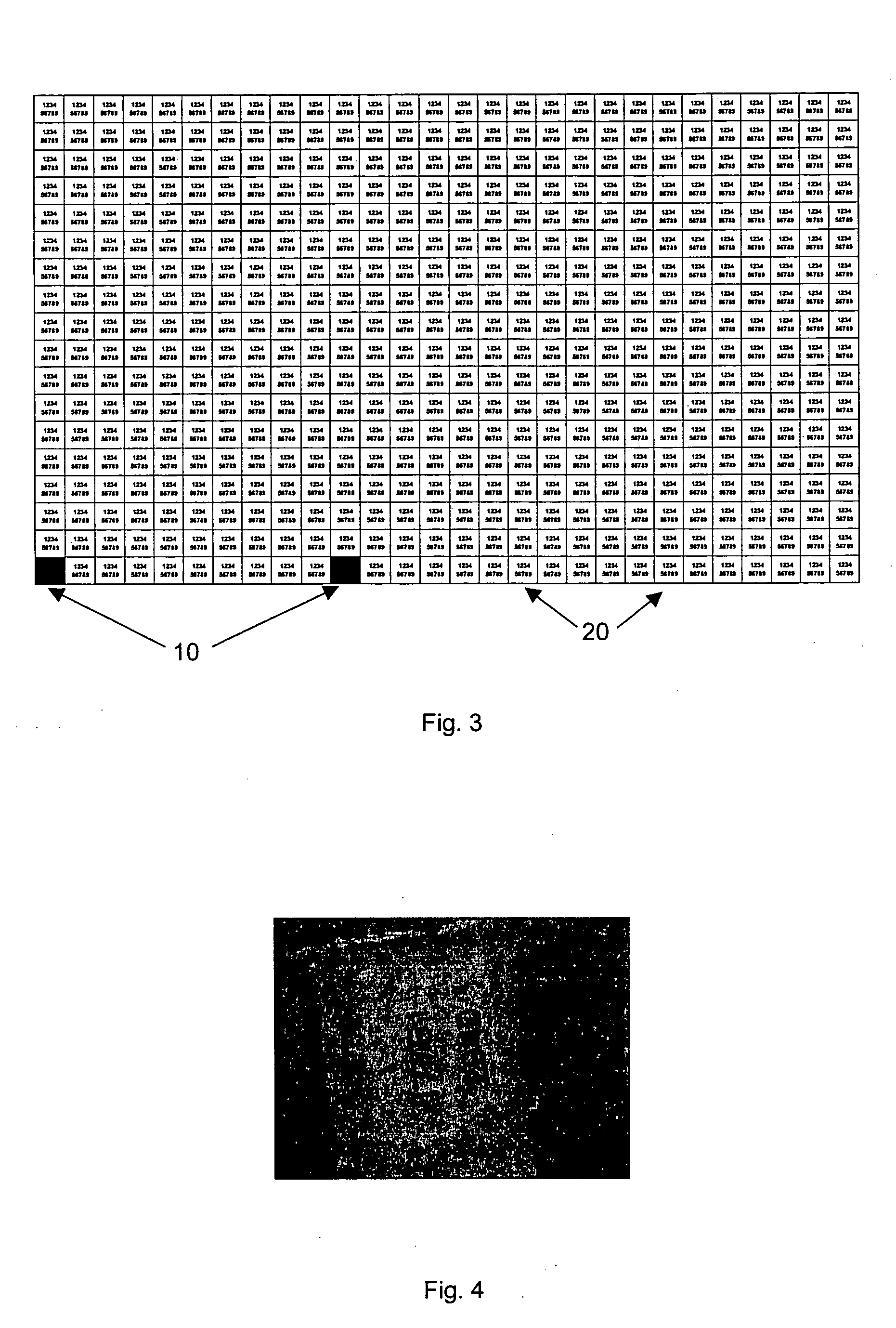
[0042] The computer controls operation of the stage and the laser system such that the laser system marks the substrate with the desired code, preferably through the use of a mask marking several areas at once. The marking can be performed in ...


PUM

PropertyMeasurementUnit
Timeaaaaaaaaaa
Transmissionaaaaaaaaaa
Adhesivityaaaaaaaaaa

Abstract

A method of producing batches of micro particles, comprises: e) affixing a substrate sheet to a support f) cutting the substrate sheet by means of a laser device to define a plurality of micro particles; g) either before, after or during the cutting the substrate sheet, marking the region of the substrate sheet defining each micro particle by means of a laser device with a code or other identifying marking, said code or other identifying marking being unique to that particular batch of micro particles to uniquely identify that batch; and h) removing the micro particles from the support by means of a solvent. Preferably a single laser device is used for cutting the substrate sheet and marking the micro particles. Alternatively, separate laser devices may be used for respectively cutting the substrate sheet and marking the micro particles.

Description

CROSS-REFERENCE TO RELATED APPLICATION [0001] This is a continuation-in-part of U.S. patent application Ser. No. 10 / 068,611 filed on Feb. 6, 2002, now abandoned.BACKGROUND OF THE INVENTION [0002] 1. Field of the Invention [0003] The present invention relates to a method for producing batches of large numbers of micro particles marked in such a manner as to uniquely identify each batch. [0004] 2. The Prior Art [0005] Known methods for producing batches of identically and uniquely marked micro particles are based on a code formed from a plurality of digits, said digits being reproduced on a substrate by means of photo reduction, the substrate then being cut to form a batch of micro particles. The required numerical code is one sequence of multiple sequences of numbers. This results in the particles being excessively large due to the inclusion of irrelevant information. [0006] Current laser marking techniques are based on substrates typically used in the micro-electronics industry to m...

Claims


Application Information

Patent Timeline
IPC IPC(8): B29B9/04B29B9/12
CPCB29B9/04B29B9/12B29B2009/125Y10T156/1064Y10T156/1085Y10T156/1082Y10T156/1075
Inventor CLEARY, MICHAEL
Owner CLEARY MICHAEL
Why Eureka
Try Eureka