Transport network and method

a transport network and transport element technology, applied in the field of telecommunication networks, can solve the problems of increasing the cost of support and equipment both in the network and in the subtending network elements, and the physical port of the ip network is required to achieve channelization, the effect of improving the external representation and reducing the amount of physical port channelization

Inactive Publication Date: 2006-11-07
FUJITSU LTD
View PDF40 Cites 52 Cited by
  • Summary
  • Abstract
  • Description
  • Claims
  • Application Information

AI Technical Summary

Benefits of technology

[0013]Another technical advantage of the present invention includes providing an improved external representation for the transport network. In particular, the transport network is represented as sets of port groups with internally managed connectivity. Port groups are internally defined and each represented as a single entity providing connectivity through the transport network. Accordingly, the external network treats the transport network as a set of distinct elements.
[0014]Still another technical advantage of the present invention includes providing an improved transport element for the transport network. In particular, the transport element includes a port group with at least point-to-multipoint connectivity between the ports. For mesh topologies, multipoint-to-multipoint connectivity is provided for external point-to-multipoint connectivity. Accordingly, the transport element is externally represented as a router or switch and channelization required on the physical ports is minimized. This reduces cost in terms of support and equipment in the transport network and in subtending network elements.
[0015]Still another technical advantage of the present invention includes providing secure transport elements within the transport network. In particular, the topology of the transport network is isolated from the external network. In addition, the routing models and topologies of a transport element is known only to ports of the transport element, and thus hidden from other transport elements in the network. As a result, the transport elements are isolated from one another to prevent cross contamination and intrusions between the elements and customers. Thus, the value of transport elements is increased for both customers and network owners.
[0016]Still another technical advantage of the present invention includes providing an improved architecture for nodes in the transport network. In particular, the transport nodes comprise modular building blocks to support a scalable, pay-as-you-grow, architecture. In addition, functionality of the transport elements is distributed between nodes to allow any processor in the transport network to control the element. The control processor for a transport element generates routing information for the element and distributes it to the ports of the element for traffic processing.
[0017]Still another technical advantage of the present invention includes providing a transport network and transport elements with high bandwidth efficiency. In particular, optical links are provided between ports of the transport elements in the network. Internet protocol (IP) and other packets are transported directly on the optical links using only a limited or thin transmission protocol. Accordingly, bandwidth use is maximized in the transport network and the cost of the network is minimized.
[0018]Still another technical advantage of the present invention includes providing an improved transport router, transport Ethernet switch, and transport Frame Relay switch with geographically distributed ports. The transport router includes a port group providing point-to-multipoint connectivity between a set of subtending IP routers. The transport Ethernet switch includes a port group providing point-to-multipoint connectivity between a set of subtending Ethernet switches. The transport Frame Relay switch includes a port group providing point-to-multipoint connectivity between a set of subtending Frame Relay switches. In addition, port groups may transparently interconnect any other suitable external ports, in which case the port group may be user protocol independent.

Problems solved by technology

Consequently, excessive channelization is required on physical ports of the IP network for point-to-multipoint data flows.
This leads to greater cost in terms of support and equipment both in the network and in subtending network elements.

Method used


Image

  • Transport network and method
  • Transport network and method
  • Transport network and method

Examples


Embodiment Construction

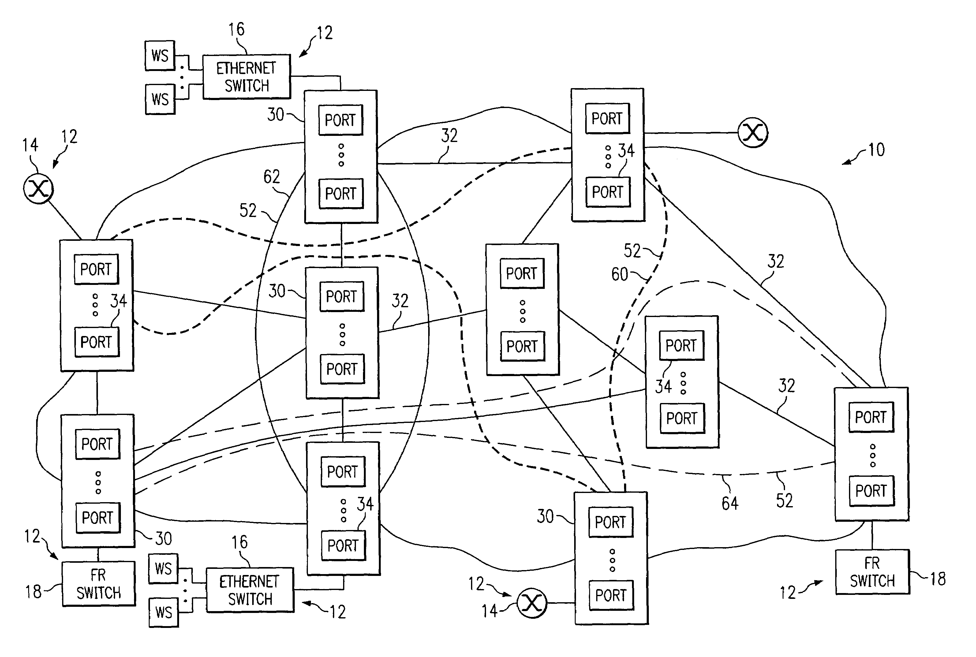
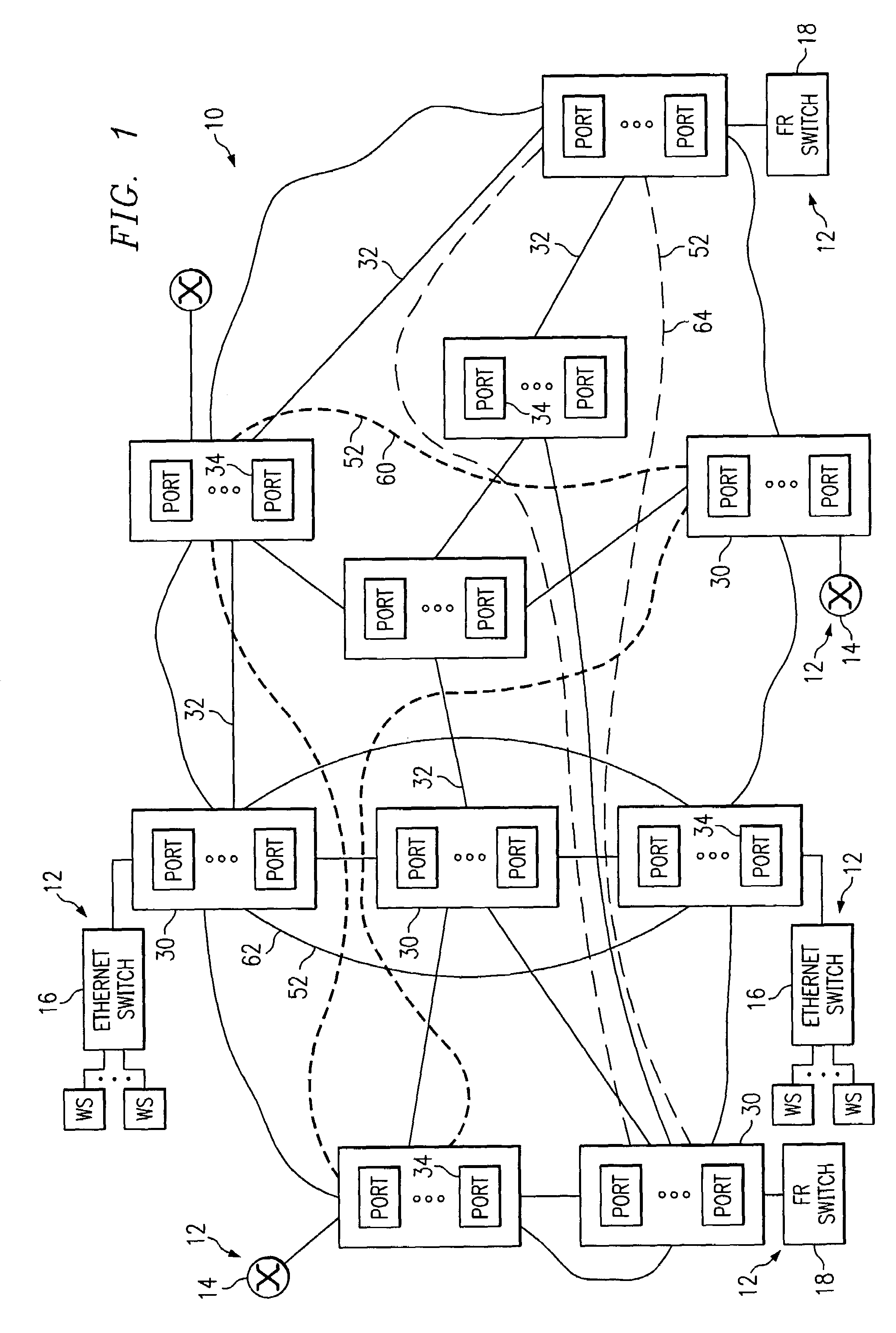
[0033]FIG. 1 illustrates a transport network 10 in accordance with one embodiment of the present invention. In this embodiment, the transport network 10 is an Internet protocol (IP) network for transporting IP and Multiple Protocol Label Switch (MPLS) packets. The transport network 10 may be any other packet-switched network operable to route, switch, and / or otherwise direct data packets based on network protocol addresses.

[0034]The transport network 10 is a private network connecting geographically distributed segments of an external network 12. The external network 12 includes one or more public and / or private networks such as the Internet, an intranet, and other suitable local area networks (LAN), wide area networks (WAN), and nodes. The external network 12 includes label switch and subtending routers 14, Ethernet switches 16, Frame Relay switches 18 and other suitable routers, switches, and nodes operable to generate and / or transport traffic. The transport network 10 communicate...


PUM


Abstract

A transport network includes a flexible topology for internally defining transport elements. The transport elements each include a port group having a plurality of geographically distributed ports from the transport network. Point-to-multipoint connectivity is defined between the ports in a port group. An identifier represents the port group as a single element to internal and/or external elements for protocol exchanges.

Description

RELATED APPLICATIONS[0001]This application claims the benefit of U.S. Provisional Application Ser. No. 60 / 202,190, entitled INTERNET PROTOCOL TRANSPORT, filed May 5, 2000 which is hereby incorporated by reference.TECHNICAL FIELD OF THE INVENTION[0002]The present invention relates generally to the field of telecommunication networks, and more particularly to a transport network and method.BACKGROUND OF THE INVENTION[0003]Telecommunication networks transport voice and data according to a variety of standards and using a variety of technologies. Circuit-switch networks such as plain old telephone service (POTS) utilize transmission paths dedicated to specific users for the duration of a call and employ continuous, fixed-bandwidth transmission. Packet-switch networks (PSNs) allow dynamic bandwidth, depending on the application, and can be divided into connectionless networks with no dedicated paths and connection-oriented networks with virtual circuits having dedicated bandwidth along a...

Claims


Application Information

Patent Timeline
Patent Type & Authority Patents(United States)
IPC IPC(8): H04L12/28H04L12/56H04L12/24H04L12/26H04L29/12H04Q11/04
CPCH04L12/2697H04L41/12H04L41/22H04L45/00H04L45/22H04L45/502H04Q11/0478H04L2012/5627H04L43/50
Inventor MO, LIWYNN, DAVID W.BUCKLIN, GEORGE E.SULLIVAN, EDWARD T.MOORE, FRANCOISJABER, ABED MOHDHARBIN, EDWARD ALTONYASEEN, NIMER IBRAHIMBARDALAI, SNIGDHO C.TERWILLIGER, DAVID W.MEZEUL, MICHAEL J.KO, KAI CHUNG
Owner FUJITSU LTD
Why Eureka
Try Eureka