Double-layer shutter control method of multi-sputtering system

a control method and multi-sputtering technology, applied in the direction of electrolysis components, vacuum evaporation coatings, coatings, etc., can solve the problems of complex changes, cross-contamination may be caused between targets, and become a conspicuous problem, so as to prevent cross-contamination

Active Publication Date: 2005-09-15
CANON ANELVA CORP
View PDF5 Cites 49 Cited by
  • Summary
  • Abstract
  • Description
  • Claims
  • Application Information

AI Technical Summary

Benefits of technology

[0013] An object of the present invention is to provide a double-layer shutter control method of a multi-sputtering system, provided with a plurality of targets in a single chamber for sputtering a multi-layer film and selecting a target by a double-layer rotating shutter mechanism, which prevents cross-contamination between targets due to the target substances etc. deposited on the shutter plates.

Problems solved by technology

When selecting a plurality of targets made of different materials by the double-layer rotating shutter mechanism and using the same for sputtering in a specific sequence, cross-contamination may be caused between targets.
This becomes a conspicuous problem.
As explained above, however, cross-contamination is a complex phenomenon changing in accordance with the number of targets, the number of holes, and other conditions.
Various types of cross-contamination occur.
Further, the method of rotation of the shutter plates of U.S. Patent Publication No. 2002 / 0064595 does not discuss at all how to deal with the target materials deposited on the shutter plates at the time of the pre-sputtering.
As described above, the method of operation of the double-layer rotating shutter mechanism disclosed in U.S. Patent Application Publication No. 2002 / 0064595 is not sufficient to deal with any cross-contamination which may occur.
This becomes a conspicuous problem.

Method used


Image

  • Double-layer shutter control method of multi-sputtering system
  • Double-layer shutter control method of multi-sputtering system
  • Double-layer shutter control method of multi-sputtering system

Examples


first embodiment

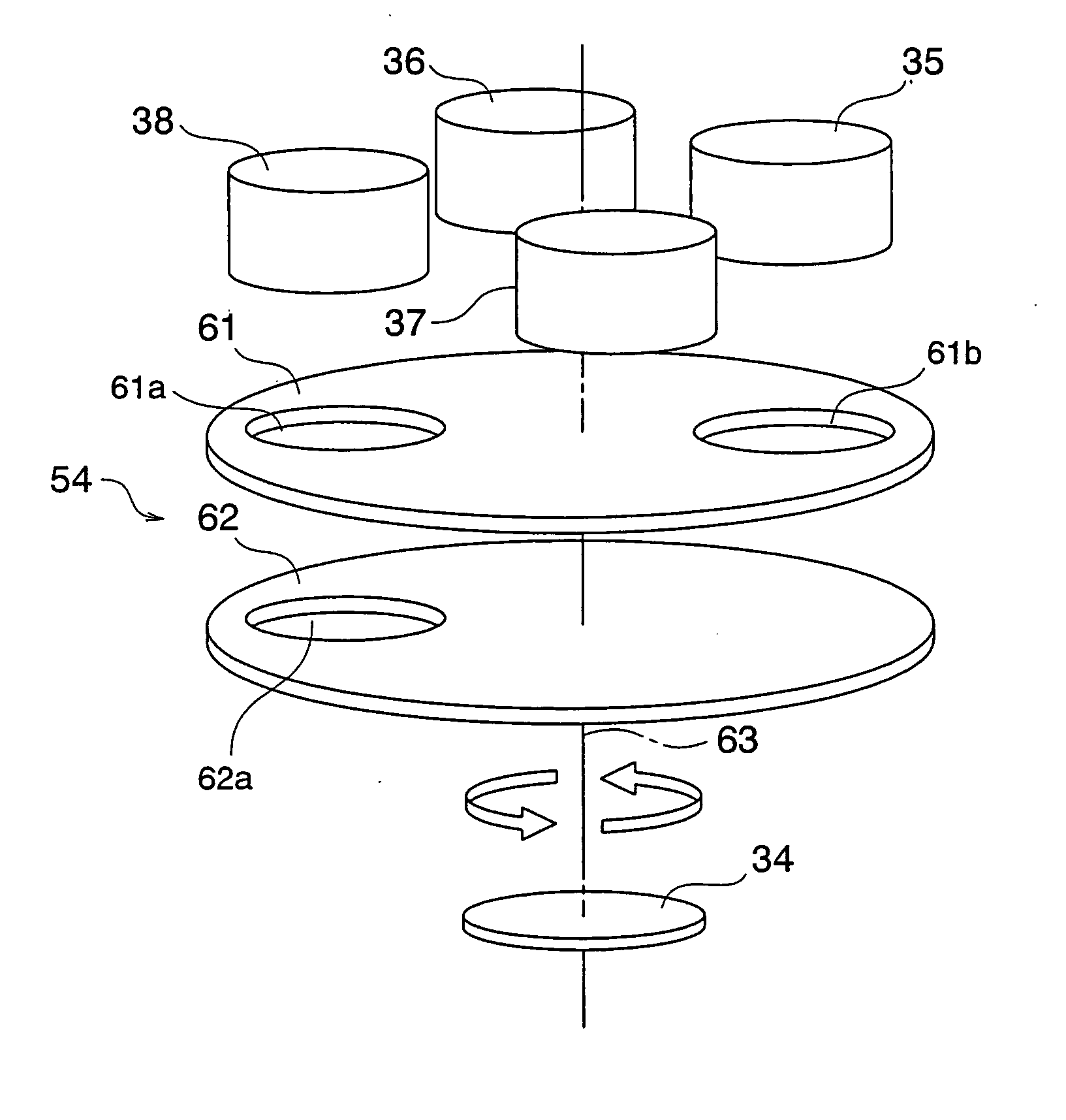
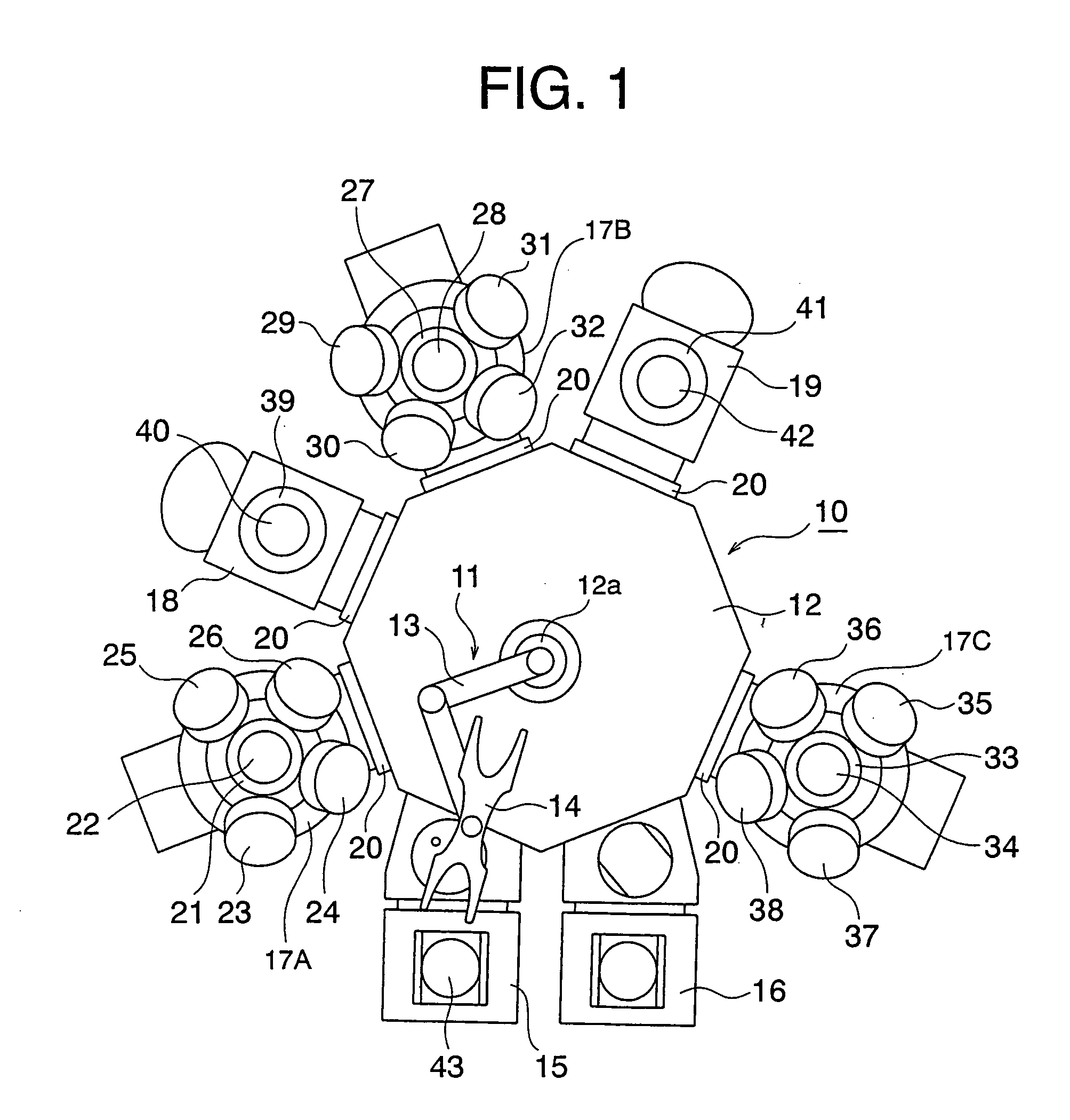
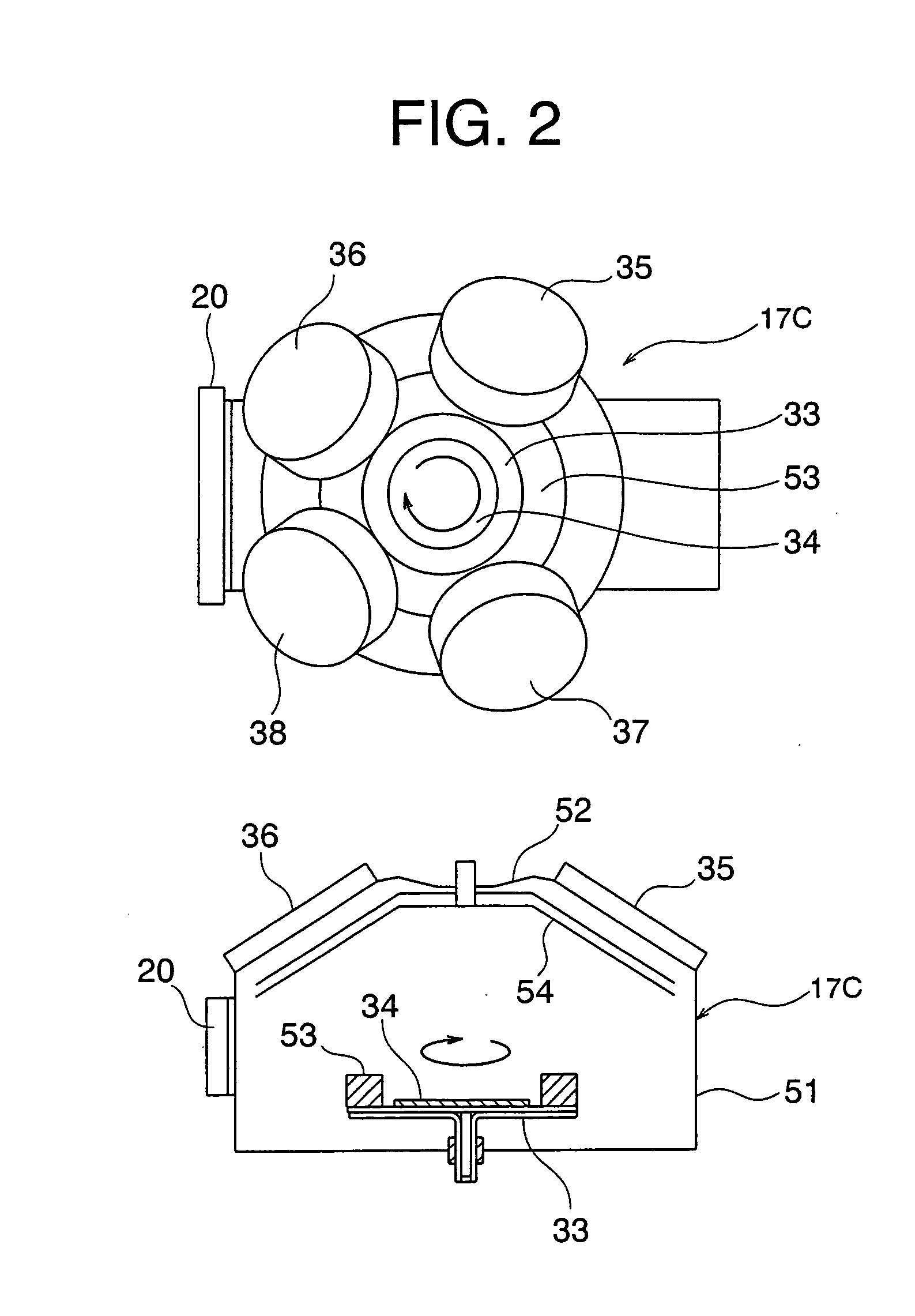
[0094] An explanation will be given of a first embodiment of the double-layer shutter control method by referring to FIG. 8 to FIG. 11. This first embodiment shows an example of four targets and single sputtering using a first shutter plate having two holes and a second shutter plate having one hole. The double-layer shutter control method according to the first embodiment is for the configuration of the system shown in FIG. 1 to FIG. 3. In FIG. 8 and FIG. 9, for convenience for conceptually explaining the embodiment, the four targets are indicated by the notations T1 to T4, the two holes of the first shutter plate 61 facing the target are indicated by the notations H1 and H2, and the single hole of the second shutter plate 62 on the substrate side is indicated by the notation H3.

[0095] The targets T1 to T4 correspond to the targets 35 to 38 shown in FIG. 3, the holes H1 and H2 correspond to the holes 61a and 61b, and the hole H3 corresponds to the hole 62a. In the first shutter pl...

second embodiment

[0104] A second embodiment of a double-layer shutter control method will be explained by referring to FIG. 12, FIG. 13, and

[0105]FIG. 14A to FIG. 14D. This second embodiment shows an example of five targets, a first shutter plate and a second shutter plate each having two holes, and co-sputtering.

[0106] In FIG. 12 and FIG. 13, the five targets are indicated by the notations T1 to T5, the two holes of the first shutter plate 61 facing the target are indicated by the notations H11 and H12, and the two holes of the second shutter plate 62 on the substrate side are indicated by the notations H13 and H14. The holes H11 and H12 in the first shutter plate 61 are formed at positions 144° apart in the clockwise direction, while the holes H13 and H14 in the second shutter plate 62 are formed at positions 144° apart in the clockwise direction. Further, in FIG. 12 and FIG. 13, the circles 101 indicate the paths of movement of the holes H11 to H14 when the shutter plates 61 and 62 rotate.

[010...

third embodiment

[0123] Next, a third embodiment of the double-layer shutter control method will be explained by referring to FIG. 15A to FIG. 15E. This third embodiment is a method of a single sputtering control using the same system configuration as that of the second embodiment explained by FIG. 12 and FIG. 13 which performs the single sputtering after the co-sputtering of the second embodiment. Accordingly, the double-layer shutter control method of the third embodiment shows an example of five targets, first and second shutter plates each having two holes, and single sputtering. Further, in the single sputtering according to the third embodiment, the pre-sputtering is performed utilizing the position where the film is finally deposited at the time when the final main sputtering in the second embodiment ends (the film deposition position at the time of the main sputtering of FIG. 14D).

[0124] In FIG. 15A to FIG. 15E, the five targets T1 to T5, the two holes H11 and H12 of the first shutter plate...


PUM

PropertyMeasurementUnit
timeaaaaaaaaaa
structureaaaaaaaaaa
magneticaaaaaaaaaa

Abstract

A double-layer shutter control method of a multi-sputtering system provided with three targets in a single chamber and a double-layer rotating shutter mechanism having shutter plates which independently rotate and have holes formed therein, comprising selecting a target by a combination of holes of a first shutter plate and a second shutter plate and uses the selected target for a pre-sputtering step and a main sputtering step with continuous discharge so as to deposit a film on a substrate, whereby it is possible to prevent cross-contamination between targets due to target substances etc. deposited on the shutter plates.

Description

BACKGROUND OF THE INVENTION [0001] 1. Field of the Invention [0002] The present invention relates to a shutter control method for a multi-sputtering system. It also relates to a double-layer shutter control method suitable for preventing cross-contamination in a multi-sputtering system providing a plurality of targets made of different materials in a single chamber and forming a multi-layer film utilizing a double-layer rotating shutter mechanism. [0003] 2. Description of the Related Art [0004] The assignee previously proposed a magnetic multi-layer film-forming system (U.S. Patent Application Publication No. 2002 / 0064595). When producing a giant magnetoresistance (GMR) or tunnel magnetoresistance (TMR) head, MRAM, etc., this magnetic multi-layer film-forming system can form a required multi-layer film in a single chamber by sputtering from the lowermost layer to the uppermost layer on a substrate continuously without interruption and can deposit a large number of magnetic films at ...

Claims


Application Information

Patent Timeline
Patent Type & Authority Applications(United States)
IPC IPC(8): C23C14/34C23C14/32C23C14/54C23C14/56
CPCC23C14/3464C23C14/54C23C14/34
Inventor NOMURA, SHUJIMIYOSHI, AYUMUMIKI, HIROSHI
Owner CANON ANELVA CORP
Why Eureka
Try Eureka