Method for particle production

a particle and particle technology, applied in the field of particle production, can solve the problems of increasing production cost and excessive particle size, and achieve the effects of low cost, high throughput and good reliability

Inactive Publication Date: 2006-08-22
CLEARY MICHAEL
View PDF26 Cites 12 Cited by
  • Summary
  • Abstract
  • Description
  • Claims
  • Application Information

AI Technical Summary

Benefits of technology

[0009]a) affixing a metal or plastic substrate sheet to a support, the sheet being constructed such that the metal can be evaporated by laser action, i.e., etching, without affecting the polymer layer and that such evaporation of the metal will form digits with good legibility when viewed under magnification;
[0029]Preferably, the arrangement of the spreadsheet is set up to maximize the number of cells printed on the film. Advantageously, the step of cutting may comprise the alignment of the laser on the film by using count marks on each frame of the film to locate the frame under the laser. Also, the blacking out of cells at pre-set positions on the spreadsheet enables the use of a vision system to control the laser by detecting the blacked out cells and making adjustments to the laser so that the laser cuts precisely around each code.

Problems solved by technology

This results in the particles being excessively large due to the inclusion of irrelevant information.
The prior art method for producing micro particles comprise a number of separate processes which increases the cost of production.

Method used


Image

  • Method for particle production
  • Method for particle production
  • Method for particle production

Examples


Embodiment Construction

[0039]The present invention will be described further, by way of several non-limiting examples of a method of producing a batch of micro particles in accordance with the invention.

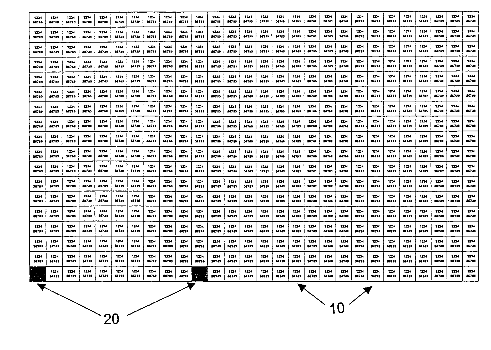
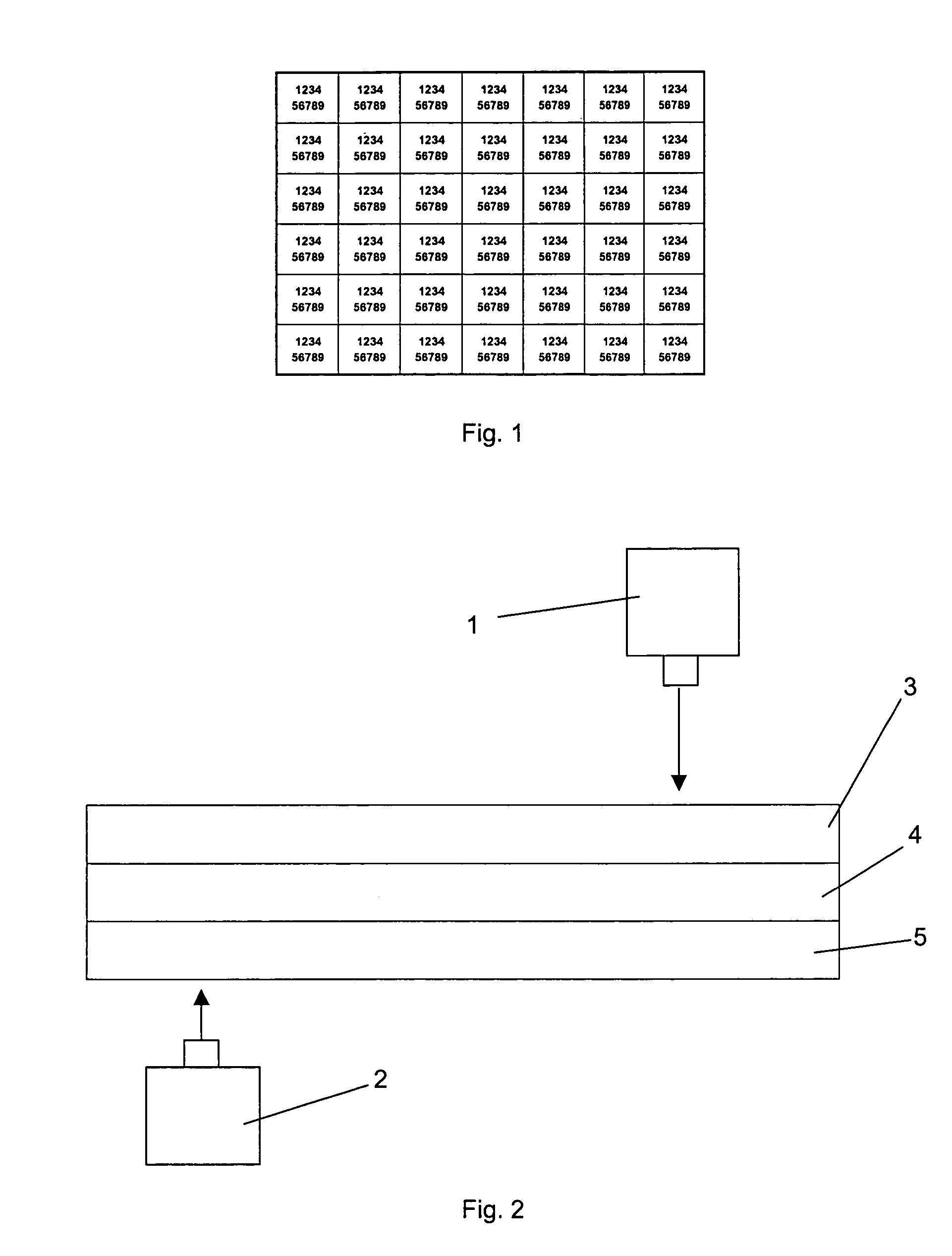
[0040]A sheet of suitable substrate typically 30 cm by 30 cm, such as a plastic / metal laminate with the metal layer applied via vacuum deposition or a plastic sheet, is adhered to a flat and inert support, preferably a flat sheet of glass by means of a suitable adhesive. A spray adhesive such as 3M Spray Mount Adhesive has been found to be particularly suitable.

[0041]The support, along with the substrate adhered thereto, is mounted on a stage movable in a plane perpendicular to a laser system. Movement of the stage in x-y coordinates is controlled by a computer.

[0042]The computer controls operation of the stage and the laser system such that the laser system marks the substrate with the desired code, preferably through the use of a mask marking several areas at once. The marking can be performed in several...


PUM

PropertyMeasurementUnit
thickaaaaaaaaaa
temperatureaaaaaaaaaa
lengthaaaaaaaaaa

Abstract

A method of producing batches of micro particles includes affixing a substrate sheet to a support and cutting the substrate sheet with a laser device to define a plurality of micro particles. Before, after or during the cutting of the substrate sheet, the region of the substrate sheet defining each micro particle is marked with a code or other identifying marking using a laser device. The code or other identifying marking is unique to the particular batch of micro particles to uniquely identify that batch. The micro particles are removed from the support by a solvent. Preferably, a single laser device is used for cutting the substrate sheet and marking the micro particles. Alternatively, separate laser devices may be used for cutting the substrate sheet and marking the micro particles.

Description

CROSS-REFERENCE TO RELATED APPLICATION[0001]This is a continuation-in-part of U.S. patent application Ser. No. 10 / 068,611 filed on Feb. 6, 2002, now abandoned.BACKGROUND OF THE INVENTION[0002]1. Field of the Invention[0003]The present invention relates to a method for producing batches of large numbers of micro particles marked in such a manner as to uniquely identify each batch.[0004]2. The Prior Art[0005]Known methods for producing batches of identically and uniquely marked micro particles are based on a code formed from a plurality of digits, said digits being reproduced on a substrate by means of photo reduction, the substrate then being cut to form a batch of micro particles. The required numerical code is one sequence of multiple sequences of numbers. This results in the particles being excessively large due to the inclusion of irrelevant information.[0006]Current laser marking techniques are based on substrates typically used in the micro-electronics industry to manufacture s...

Claims


Application Information

Patent Timeline
Patent Type & Authority Patents(United States)
IPC IPC(8): G03C5/00B23K26/02G09F3/02B29B9/04B29B9/12
CPCB29B9/04B29B9/12B29B2009/125Y10T156/1064Y10T156/1085Y10T156/1082Y10T156/1075
Inventor CLEARY, MICHAEL
Owner CLEARY MICHAEL
Why Eureka
Try Eureka