Image processing device, image forming apparatus including same, image processing method, and image processing program

a technology of image forming apparatus and image processing method, which is applied in the direction of image enhancement, visual presentation using printers, instruments, etc., can solve the problems of unsuitable print system for image forming apparatus such as copiers, unnatural and odd output images, and affecting the legibility of the image, so as to reduce the consumption of image forming material, reduce the effect of unnatural and odd parts

Inactive Publication Date: 2009-02-05
RICOH KK
View PDF27 Cites 28 Cited by
  • Summary
  • Abstract
  • Description
  • Claims
  • Application Information

AI Technical Summary

Benefits of technology

[0016]In view of the foregoing, exemplary embodiments of the present invention provide an image processing device capable of reducing unnatural and odd parts from an output image when the density of the output image is partially reduced so as to reduce consumption of an image forming material, and improving legibility of a character image of which the outline is not detected as an edge part. Exemplary embodiments of the present invention further provide an image forming apparatus including the image processing device, an image processing method, and an image processing program.
[0017]In one exemplary embodiment, an image processing device includes an image signal reception unit configured to receive an image signal of an image to be processed; a density reduction area detector configured to detect a density reduction area satisfying predetermined image density reduction requirements in the image to be processed based on the image signal received by the image signal reception unit; a specific image area detector configured to detect a specific image area satisfying predetermined specific image requirements different from the predetermined image density reduction requirements in the image to be processed based on the image signal received by the image signal reception unit; and a density controller configured to reduce density of the density reduction area detected by the density reduction area detector in a non-specific image area other than the specific image area detected by the specific image area detector, and to not reduce density of the density reduction area in the specific image area.
[0019]Yet another exemplary embodiment provides an image processing method including receiving an image signal of an image to be processed; detecting a density reduction area satisfying predetermined image density reduction requirements in the image to be processed based on the image signal received in the receiving; detecting a specific image area satisfying predetermined specific image requirements different from the predetermined image density reduction requirements in the image to be processed based on the image signal received in the receiving; and reducing density of the density reduction area detected in the detecting the density reduction area in a non-specific image area other than the specific image area detected in the detecting the specific image area, and not reducing density of the density reduction area in the specific image area.

Problems solved by technology

However, because the image is output after reducing density in the above-described methods, the quality of the output image is degraded compared to that in the normal output mode.
However, in the print system, the above-described processing is not performed on an input image with no object data, such as a scanner image read by an image reading device.
Therefore, the print system is not applicable to an image forming apparatus such as a copier, in which the image reading device is included.
Specifically, a higher degree of unnaturalness is found in an output image of a face image area including a face image and a surrounding image when the density of an edge part is high and that of a non-edge part is low.
Consequently, only hair and pupils are emphasized, resulting in a higher degree of unnaturalness.
In addition, when contrast between a character image and an adjacent image is low, the outline of the character image may not be detected as an edge part.
Particularly, for example, in a map image in which a very small character image indicating an address and a name is included and the contrast between the character image and an adjacent image is low, it is very difficult to detect the outline of the character image as an edge part.
Particularly when the text includes a numeric image, which is unlike a character image which indicates a word of a text, it is very difficult to identify a character indicated by the numeric image by referring to the surrounding text before and after the numeric image.

Method used


Image

  • Image processing device, image forming apparatus including same, image processing method, and image processing program
  • Image processing device, image forming apparatus including same, image processing method, and image processing program
  • Image processing device, image forming apparatus including same, image processing method, and image processing program

Examples


Embodiment Construction

[0043]In describing exemplary embodiments illustrated in the drawings, specific terminology is employed for the sake of clarity. However, the disclosure of this patent specification is not intended to be limited to the specific terminology so selected, and it is to be understood that each specific element includes all technical equivalents that operate in a similar manner and achieve a similar result.

[0044]Exemplary embodiments of the present invention are now described below with reference to the accompanying drawings.

[0045]In a later-described comparative example, exemplary embodiment, and exemplary variation, for the sake of simplicity the same reference numerals will be given to identical constituent elements such as parts and materials having the same functions, and redundant descriptions thereof omitted unless otherwise stated.

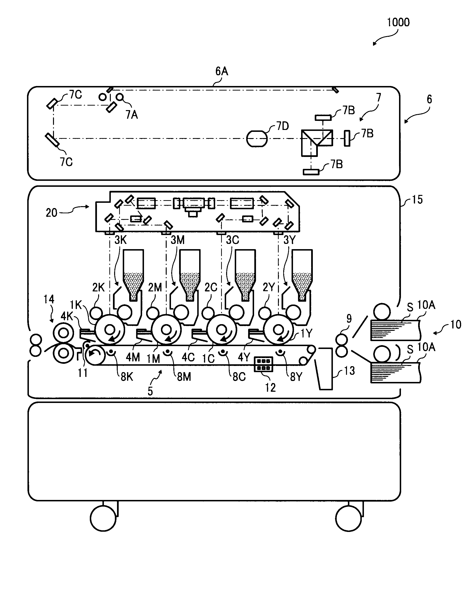
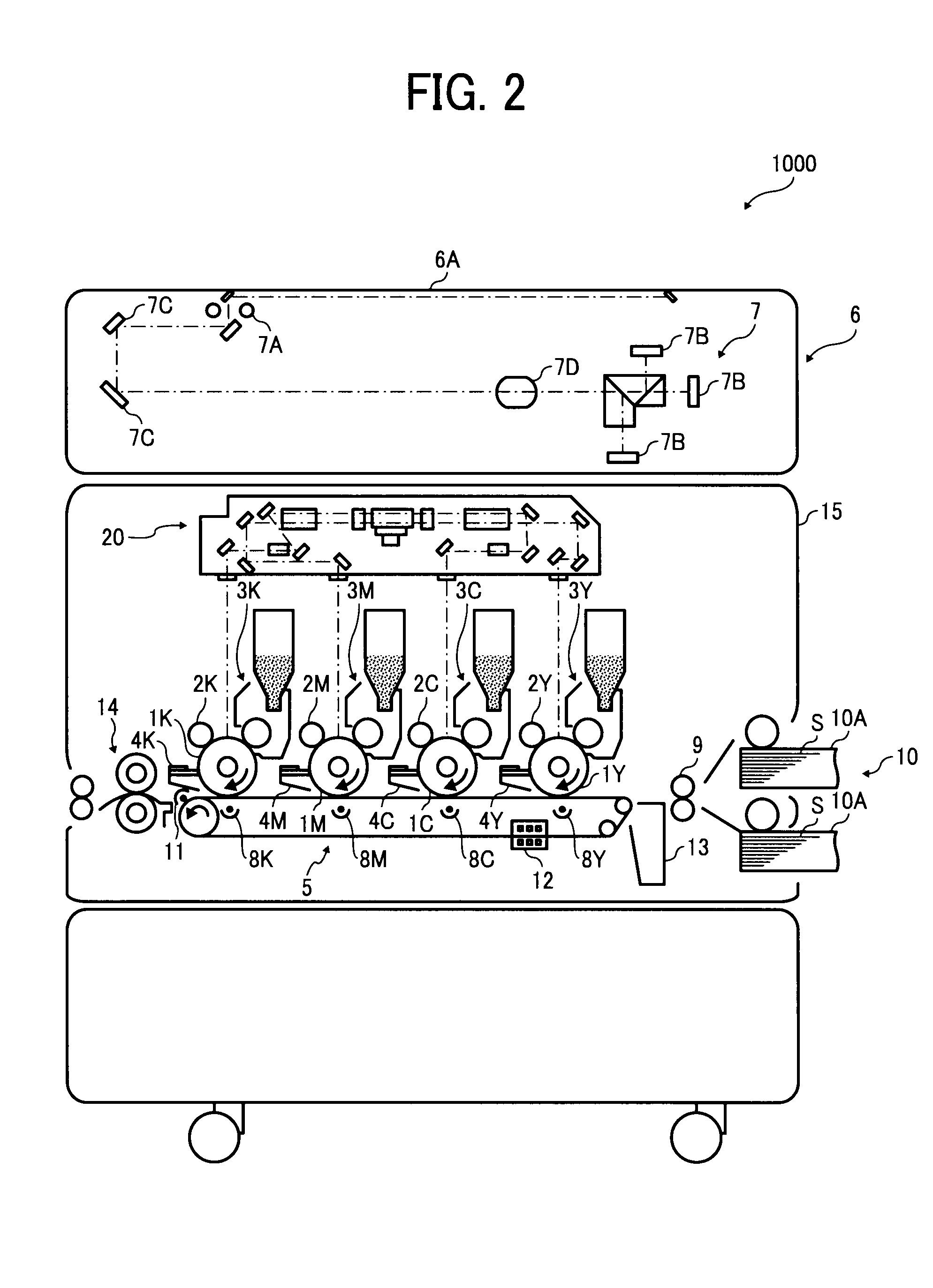
[0046]Typically, but not necessarily, paper is the medium from which is made a sheet on which an image is to be formed. It should be noted, however, tha...


PUM


Abstract

An image processing device including an image signal reception unit configured to receive an image signal of an image to be processed; a density reduction area detector configured to detect a density reduction area satisfying predetermined image density reduction requirements in the image to be processed based on the image signal; a specific image area detector configured to detect a specific image area satisfying predetermined specific image requirements different from the predetermined image density reduction requirements in the image to be processed based on the image signal; and a density controller configured to reduce density of the density reduction area detected by the density reduction area detector in a non-specific image area other than the specific image area detected by the specific image area detector, and to not reduce density of the density reduction area in the specific image area.

Description

CROSS-REFERENCE TO RELATED APPLICATIONS[0001]The present patent application is based on and claims priority pursuant to 35 U.S.C. §119 from Japanese Patent Application No. 2007-198708, filed on Jul. 31, 2007 in the Japan Patent Office, the entire contents of which are incorporated herein by reference.BACKGROUND OF THE INVENTION[0002]1. Field of the Invention[0003]Exemplary aspects of the present invention generally relate to an image processing device, an image forming apparatus including the image processing device, an image processing method, and an image processing program.[0004]2. Description of the Background[0005]Related-art image forming apparatuses, such as a copier, a facsimile machine, a printer, or a multifunction printer having two or more of copying, printing, scanning, and facsimile functions, form a toner image on a recording medium (e.g., a sheet) according to image data using an electrophotographic method. In such a method, for example, a charger charges a surface o...

Claims


Application Information

Patent Timeline
Patent Type & Authority Applications(United States)
IPC IPC(8): G06K15/02
CPCH04N1/6072H04N1/4072
Inventor SHIBAKI, HIROYUKIMIYAGI, NORIKO
Owner RICOH KK
Why Eureka
Try Eureka