

Printing with reduced outline bleeding
a printing and outline technology, applied in the field of printing images, can solve the problems of bleeding, ink accumulation, and contour lines extending parallel to the direction of main scanning
- Summary
- Abstract
- Description
- Claims
- Application Information
AI Technical Summary
Benefits of technology
Problems solved by technology
Method used
Image

Examples
first working example
C. First Working Example
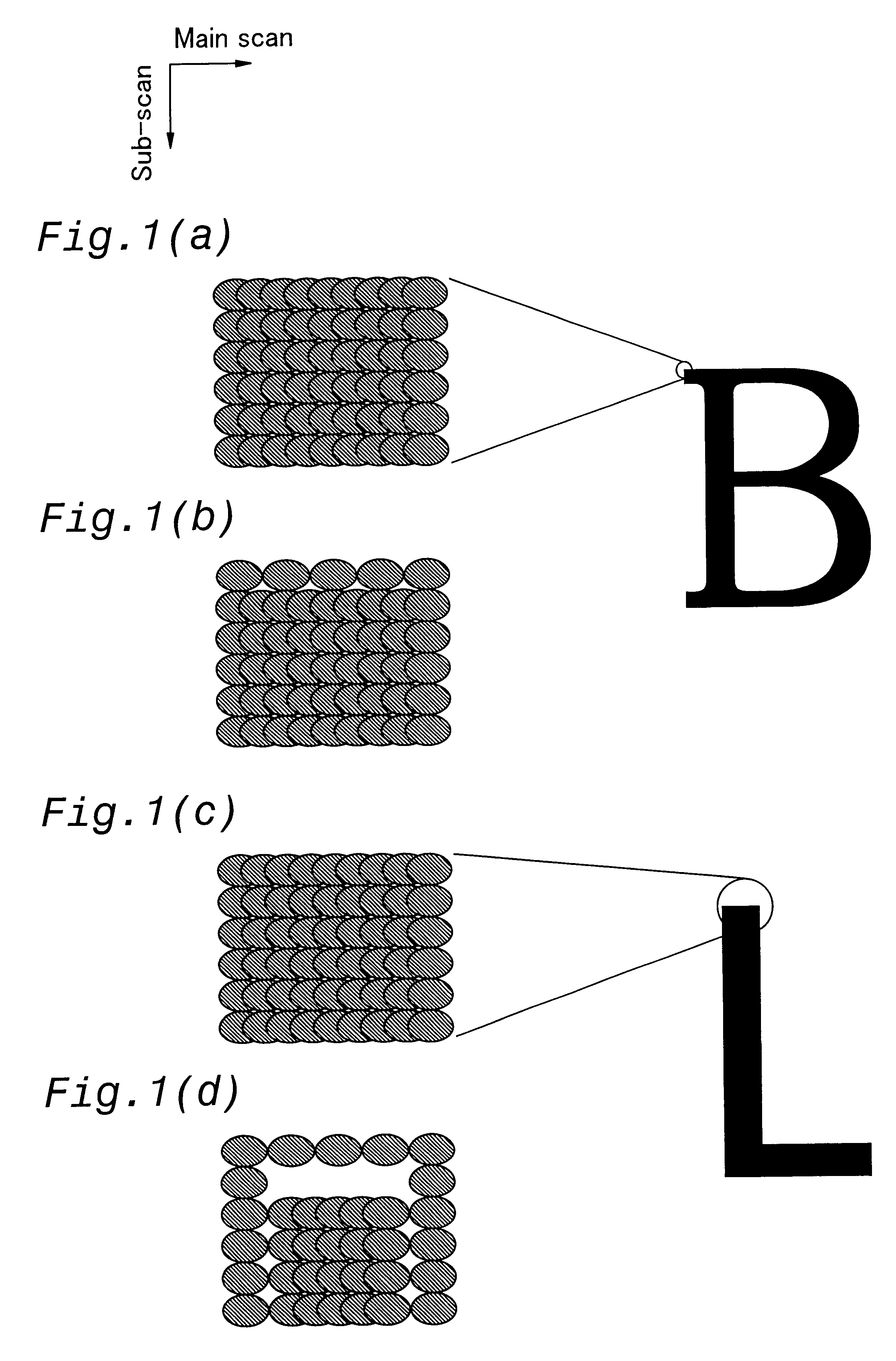
FIG. 5 is a flowchart of a dot skipping procedure performed in accordance with the first working example of the present invention. According to the first working example, every second dot in the contour lines disposed parallel to the direction of main scanning is skipped, as shown in FIG. 1b. The amount of ink is thus reduced in a systematic manner in the direction of main scanning, and less ink is deposited along the contour lines.
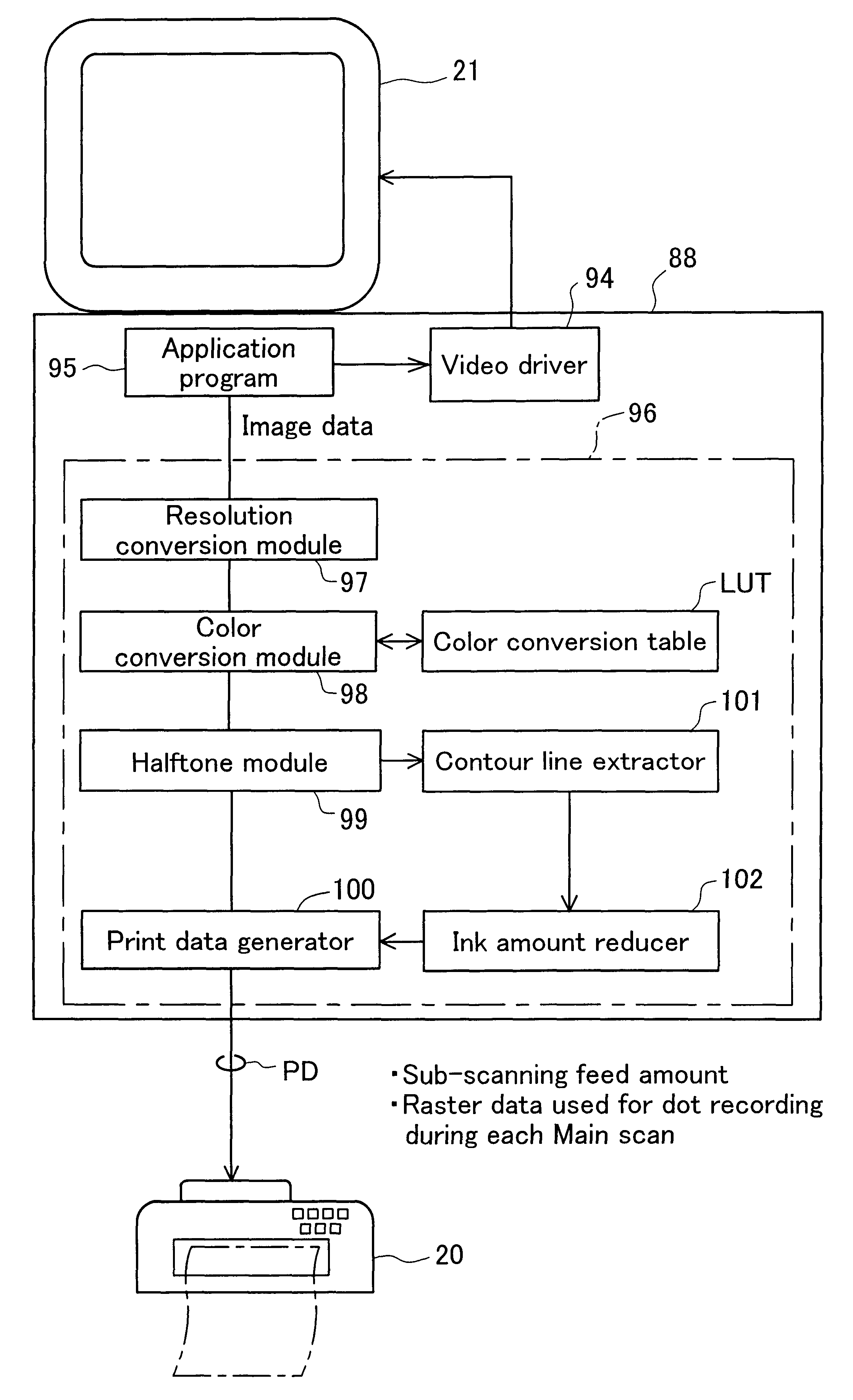
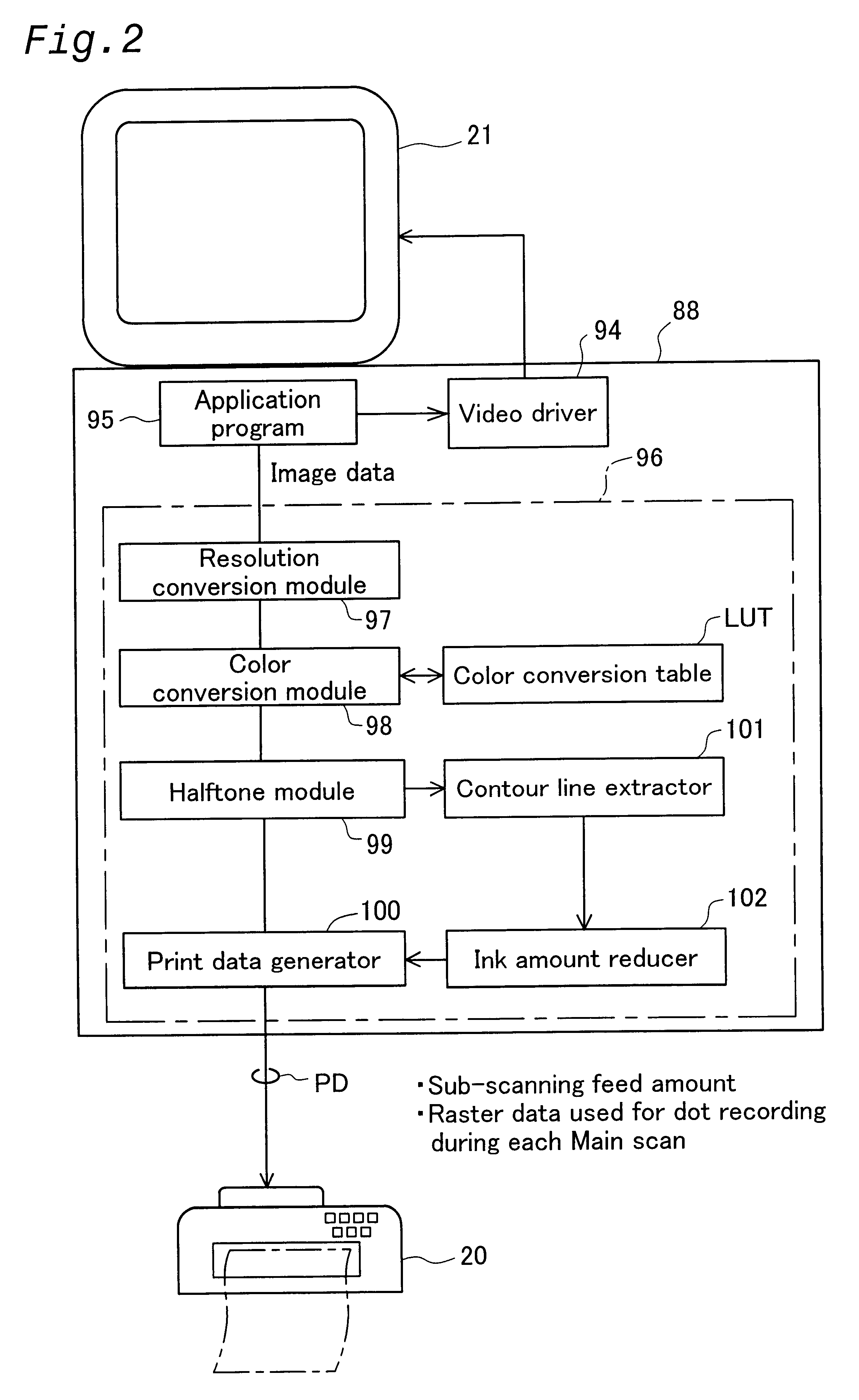
In step S101, the contour line extractor 101 extracts the contour lines that are parallel to the direction of main scanning. In the present working example, a first derivation filter such as the one shown in FIG. 6a may be used as the simplest contour line extraction filter for such extraction. This filter has directionality in the direction of sub-scan and can extract contour lines that are parallel to the direction of main scanning. As used herein, the term "contour line" refers to an area of single pixel width that defines the o...
second working example
D. Second Working Example
FIG. 9 is a flowchart of a dot skipping procedure performed in accordance with the second working example of the present invention. In the second working example, two skipping procedures are performed. In the first skipping procedure, the amount of ink is reduced for the dots designed to form pixels one row inward from a contour line, rather than on the contour line itself. It is thus possible, for example, to print high-concentration images with sharply defined outlines on plain paper with low ink absorption. The second skipping procedure involves deleting dots from a contour line and is the same procedure as the one described with reference to the first working example.
The ink amount reducer 102 performs the first skipping procedure in step S301. Such skipping is carried out in order to regularly reduce the supply of ink to the dots for forming pixels one row inward from the contour line, as described above.
FIG. 10 is a diagram illustrating the manner in w...
third working example
E. Third Working Example
The third working example differs from the above-described working examples in that the skipping procedure is varied in accordance with the print mode. The following print mode parameters are used to determine the specifics of the skipping procedure adopted in the present working example.
(1) Print resolution
(2) Ink color (selected from "all-black" and "color")
(3) Type of print medium
FIG. 15 is a diagram depicting an example of skipping performed when print resolution is higher in the direction of main scanning than in the direction of sub-scan. The drawing depicts, in enlarged form, some of the ink dots that form the letter "B" as a printed image. The drawing illustrates the manner in which some pixels are skipped when the print resolution is 720 dpi in the direction of main scanning, and 360 dpi in the direction of sub-scan. The left side of the drawing depicts the condition existing prior to the skipping procedure, and the right side of the drawing depicts ...
PUM
 Abstract
Description
Claims
Application Information