Suture device with first and second needle giudes attached to a shaft and respectively holding first and second needles

a suture device and shaft technology, applied in the field of medical devices, can solve the problems of increasing the risk of subsequent bleeding, difficulty in accessing and suturing internal tissues (such as the intima of the blood vessel or the abdominal fascia) through puncture, etc., and achieve the effect of improving safety and convenien

Inactive Publication Date: 2011-10-11
NEATSTITCH LTD
View PDF39 Cites 48 Cited by
  • Summary
  • Abstract
  • Description
  • Claims
  • Application Information

AI Technical Summary

Benefits of technology

[0008]Embodiments of the present invention that are disclosed hereinbelow provide devices and methods for suturing a puncture site in the body of a patient with enhanced safety and convenience.
[0012]The use of needles and needle guides in the manner described herein gives embodiments of the present invention substantial advantages over suturing devices known in the art. For example, ejection of the needles in the proximal direction eliminates the risk of accidentally puncturing other surfaces or organs deeper inside the body. Furthermore, because the needles remain inside the needle guides until the needle guides actually contact the cavity wall that is to be sutured, the risk that the needles will accidentally catch and suture other tissues to the cavity wall is also reduced. The needle guides may be made stiff enough to provide precise control of the locations at which the needles penetrate the cavity wall, while the needles themselves may be very thin and flexible in order to reduce trauma and bleeding when they do penetrate the tissue.

Problems solved by technology

Although the skin at the outer end of the puncture can easily be sutured, it is difficult to access and suture the internal tissues (such as the intima of the blood vessel or the abdominal fascia) through the puncture.
This mechanical technique requires the patient to remain immobilized for a long time (typically 2-8 hours), and increases the risk of subsequent bleeding.

Method used


Image

  • Suture device with first and second needle giudes attached to a shaft and respectively holding first and second needles
  • Suture device with first and second needle giudes attached to a shaft and respectively holding first and second needles
  • Suture device with first and second needle giudes attached to a shaft and respectively holding first and second needles

Examples


Embodiment Construction

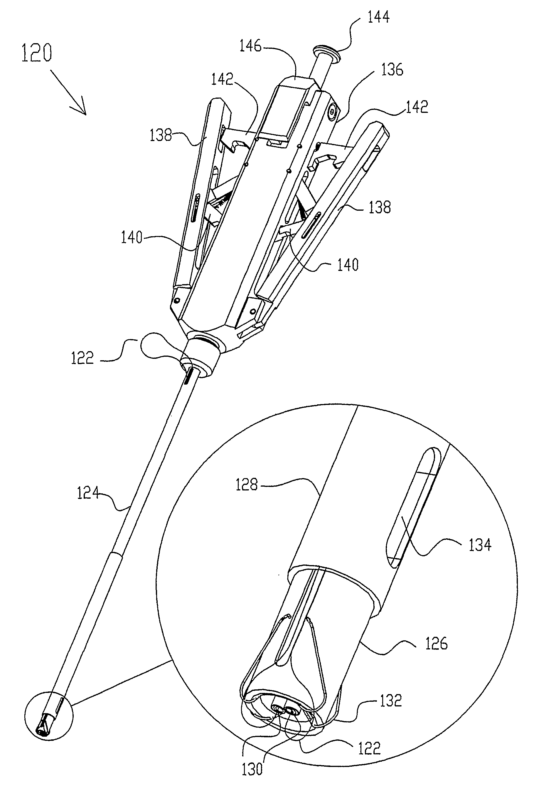
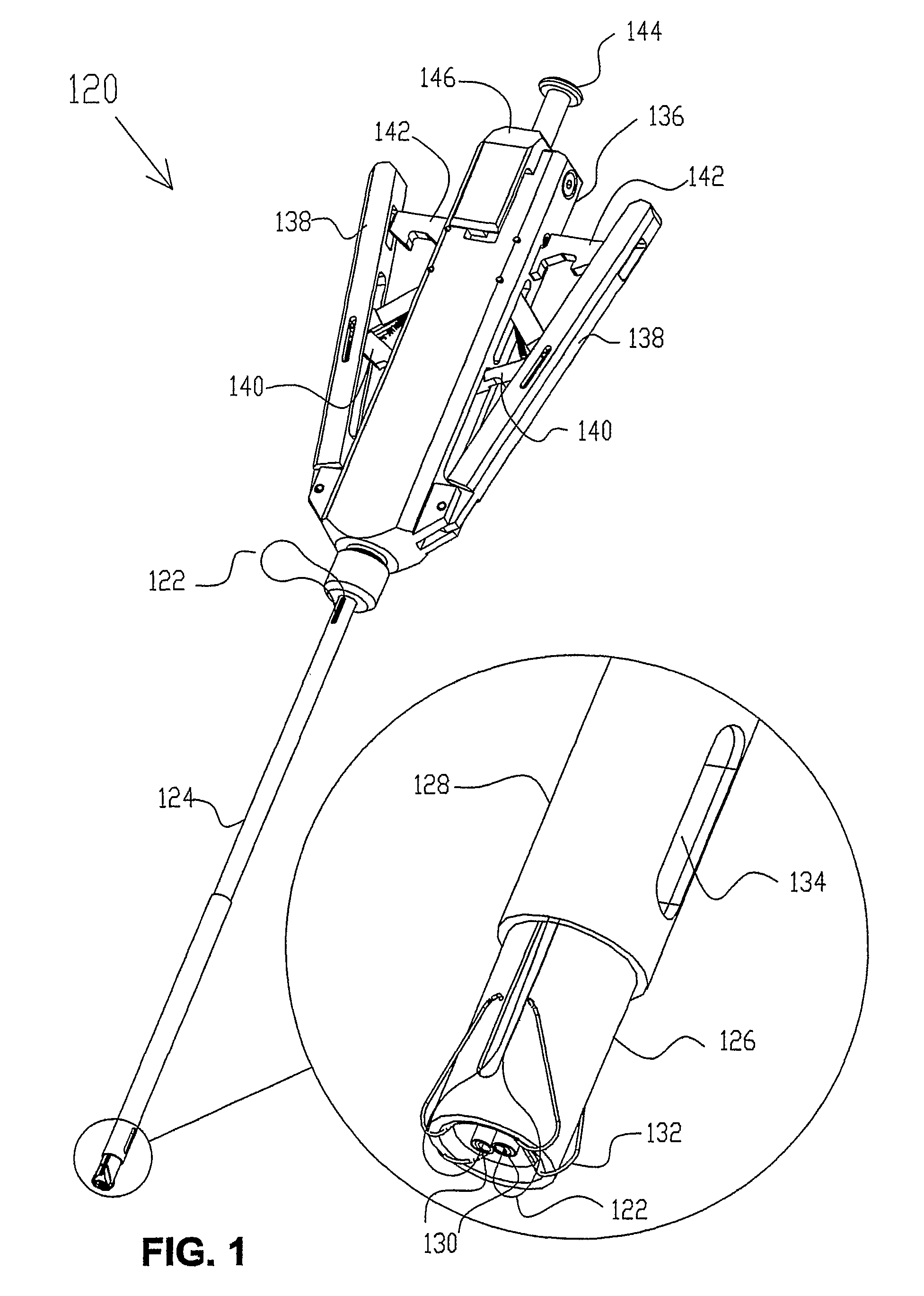
[0114]FIG. 1 is a schematic, pictorial illustration showing a device 120 for insertion of a suture 122 in body tissue, in accordance with an embodiment of the present invention. Device 120 is adapted particularly for closure of laparoscopic port puncture sites in the peritoneum, following laparoscopic surgery. Devices of this sort may also be adapted, however, for closure of punctures in blood vessels following vascular catheterization, as well as other surgical operations. Some of these alternative applications and embodiments are described further hereinbelow.

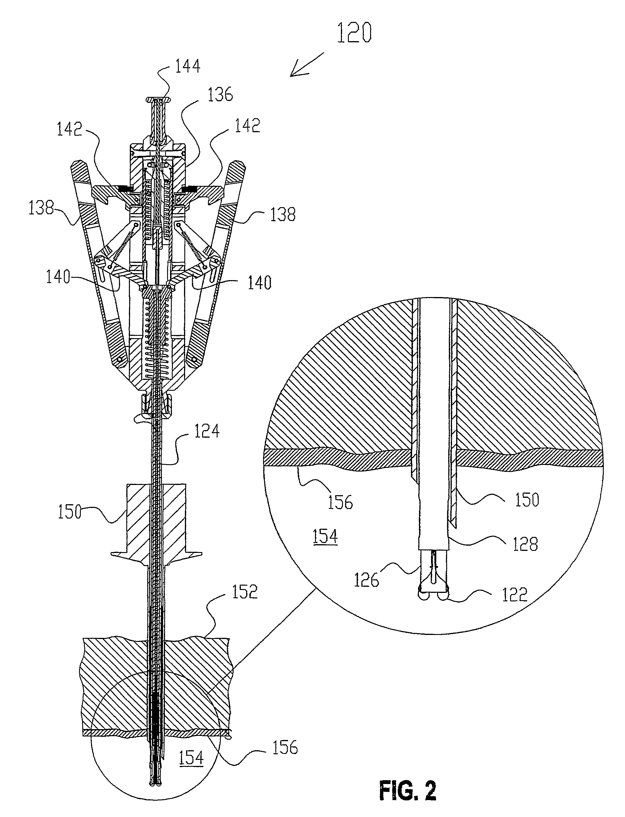
[0115]Device 120 comprises a shaft 124, whose distal end is shown enlarged in the inset in FIG. 1. The device is shown in FIG. 1 in its initial, closed configuration. In this configuration, shaft 124 is inserted through the puncture, as described hereinbelow. The shaft comprises a distal tube 126, which holds needle guides 130. The needle guides comprise a resilient material, typically a superelastic material, such as Nitinol...


PUM


Abstract

A suture insertion device (120) includes a shaft (124), which is adapted to be inserted into a body cavity (154). First and second needles (160) hold respective first and second ends of a suture thread (122). First and second needle guides (130) are attached to the shaft and respectively hold the first and second needles. The needle guides have a first operative configuration in which the needle guides are held parallel to the axis of the shaft for insertion of the shaft into the body cavity and a second operative configuration in which the needle guides are deployed outward from the shaft within the body cavity so as to point the needles in a proximal direction. An ejector (164) is operative to eject the needles from the needle guides in the second operative configuration so as to cause the needles to penetrate tissue (156) adjoining the body cavity.

Description

CROSS-REFERENCE TO RELATED APPLICATION[0001]This application claims the benefit of U.S. Provisional Patent Application 60 / 573,631, filed May 21, 2004, which is incorporated herein by reference.FIELD OF THE INVENTION[0002]The present invention relates generally to medical devices, and specifically to minimally-invasive suturing devices and techniques.BACKGROUND OF THE INVENTION[0003]Minimally-invasive surgical procedures frequently involve insertion of instruments into a body cavity through a tissue puncture site. Examples of such procedures include insertion of vascular catheters through a puncture site in a blood vessel and insertion of laparoscopic instruments through a puncture site in the abdominal wall. (In the context of the present patent application and in the claims, the term “cavity” is used broadly to refer to any and all sorts of volumes inside the body, including lumens, such as blood vessels.) It is desirable, in order to facilitate healing and reduce complications, to...

Claims


Application Information

Patent Timeline
Patent Type & Authority Patents(United States)
IPC IPC(8): A61B17/04A61B17/00A61B17/06
CPCA61B17/0469A61B17/0057A61B2017/00637A61B2017/00663A61B2017/047A61B2017/0472A61B17/0482
Inventor KEREN, DVIRLORE, RAMI
Owner NEATSTITCH LTD
Why Eureka
Try Eureka