Hybrid braided stent

A body and filament technology, applied in the field of hybrid braided stents, can solve the problems of poor safety of carotid artery stents, and achieve the effect of not being easily broken, good positioning, and even plaque stress

Pending Publication Date: 2021-02-23
SUZHOU ZENITH VASCULAR SCITECH LTD
View PDF1 Cites 6 Cited by
  • Summary
  • Abstract
  • Description
  • Claims
  • Application Information

AI Technical Summary

Problems solved by technology

[0008] The purpose of the present invention is to provide a hybrid braide

Method used


Image

  • Hybrid braided stent
  • Hybrid braided stent
  • Hybrid braided stent

Examples


Embodiment 1

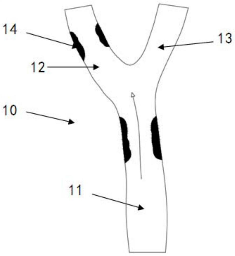
[0047] figure 1 It is a schematic structural diagram of the carotid artery 10 of the embodiment of the present invention. Such as figure 1As shown, the carotid artery 10 is divided into a common carotid artery 11 , an internal carotid artery 12 and an external carotid artery 13 , and the common carotid artery 11 , the internal carotid artery 12 and the external carotid artery 13 form a Y-shaped bifurcation structure. The blood of the common carotid artery 11 flows into the internal carotid artery 12 and the external carotid artery 13 respectively at the Y-shaped bifurcation structure. Among them, the blood of the internal carotid artery 12 mainly flows to the brain, and the blood of the external carotid artery 13 mainly supplies the facial organs. There are plaques 14 on the common carotid artery 11 and the internal carotid artery 12, and the plaques 14 lead to narrowing of blood vessels and affect blood circulation. Therefore, it is necessary to install a stent at the lesi...

Embodiment 2

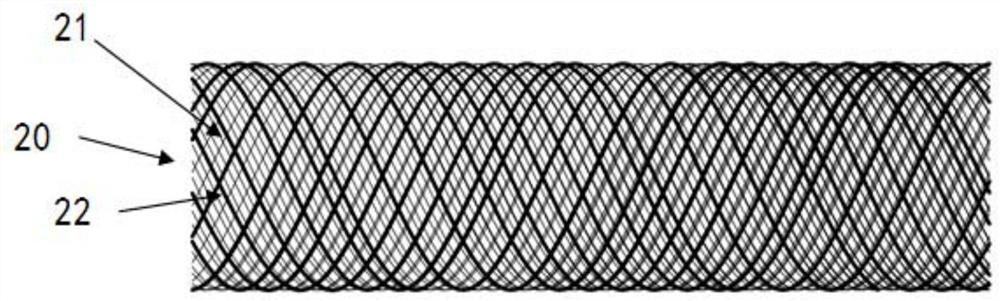
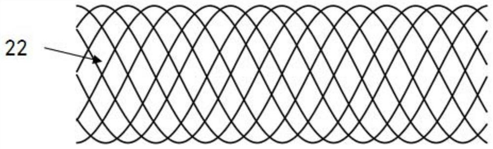
[0074] Such as Figure 18 As shown, the bracket body 20 of this embodiment is basically the same as the bracket body 20 of the first embodiment. For example, the stent body 20 of this embodiment is the same as the first embodiment, and is also a tubular structure formed by interlacing at least two filaments, and the end areas of at least two filaments are not completely the same. The materials of at least two filaments are not exactly the same. The stent body 20 is braided by two or three kinds of filaments with different end areas.

[0075] The difference between the stent body 20 of this embodiment and the stent body 20 of Embodiment 1 is that the stent body 20 of this embodiment has at least two sections, and the braiding angles of each section are not exactly the same, so as to better adapt to changes in blood vessels. .

[0076] For example, the stent body 20 of this embodiment has two sections, Figure 18 The braiding angle a of the middle left section is larger, and...


PUM

PropertyMeasurementUnit
Diameteraaaaaaaaaa
Diameteraaaaaaaaaa
Diameteraaaaaaaaaa

Abstract

The invention belongs to the technical field of medical apparatus and instruments, and particularly relates to a hybrid braided stent. The hybrid braided stent comprises a stent body, and the stent body is of a single-layer structure. The stent body is of a cylindrical structure formed by weaving at least two wire bodies in a staggered mode, and end areas of the at least two wire bodies are not completely the same. The stent body of the hybrid braided stent is formed by weaving at least two wire bodies in a staggered mode, and the end areas of the at least two wire bodies are different. The wire bodies with large end areas enable the stent body to have good supporting force, so that the stent body is tightly attached to a blood vessel, and the good positioning is achieved. The wire bodieswith small end areas enable meshes of the stent body to be small, after the stent body is installed in the blood vessel, plaques are stressed more evenly and are not prone to breakage, and even if theplaques are broken, the stent body can effectively prevent fragments of the plaques from flowing to the downstream of the blood vessel. In conclusion, compared with the prior art, the use safety of the sent body is better.

Description

technical field [0001] The invention belongs to the technical field of medical devices, and in particular relates to a hybrid braided stent. Background technique [0002] Cerebrovascular disease is a major disease that threatens human health today, and is the third leading cause of death after cardiovascular disease and tumors. Among them, 25% of ischemic strokes are related to carotid artery stenosis or occlusion. [0003] The treatment of carotid artery stenosis is mainly divided into drug therapy, carotid endarterectomy, and carotid artery stenting. Among them, carotid artery stenting has the advantages of simplicity, less trauma, and fewer complications, and is currently one of the effective methods for treating carotid artery stenosis. The carotid artery stent is generally installed in the common carotid artery and the internal carotid artery. After the carotid artery stent is opened, it will stretch the blood vessel narrowed by the disease and restore the normal blood...

Claims


Application Information

Patent Timeline
IPC IPC(8): A61F2/06A61F2/07A61F2/90
CPCA61F2/06A61F2/07A61F2/90A61F2250/0028A61F2250/0017A61F2230/0067A61F2/0105A61F2/013A61F2220/0025A61F2230/0069
Inventor 焦力群李爽夏洁汪泽辉
Owner SUZHOU ZENITH VASCULAR SCITECH LTD
Why Eureka
Try Eureka