This helps you quickly interpret patents by identifying the three key elements:
Problems solved by technology
Method used
Benefits of technology
Problems solved by technology
In all of these, the problem is not the force required to dislodge the cork stopper, but rather it is in the means of applying it to the soft and frangible part of the cork which is exposed.
Teeth forced into the uncompressed cork can tear or fracture the cap, leaving even less to work with.
Most champagne
Method used
Image
Click on the blue label to locate the original text in one second.
Reading with bidirectional positioning of images and text.
Examples
Embodiment Construction
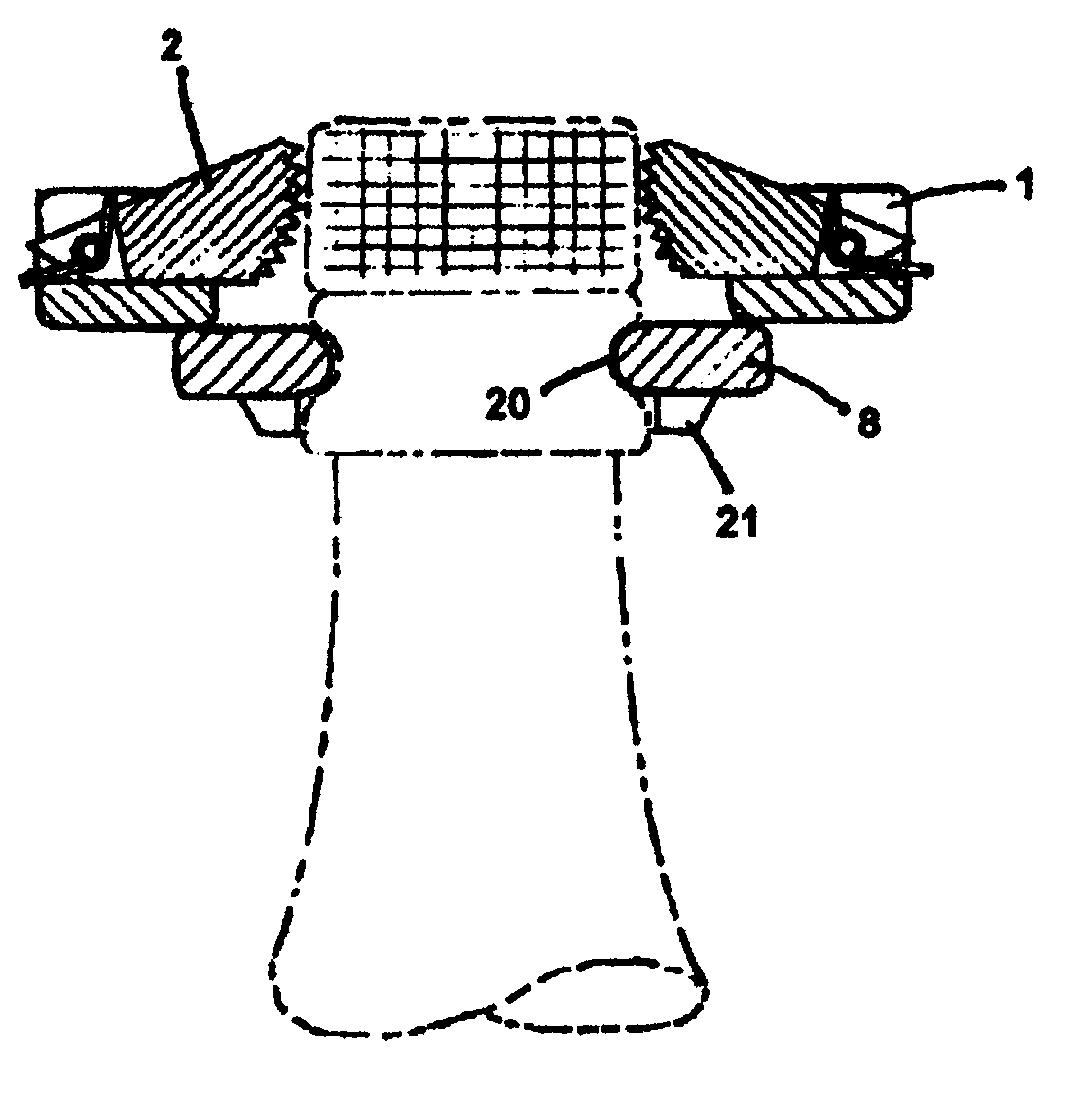
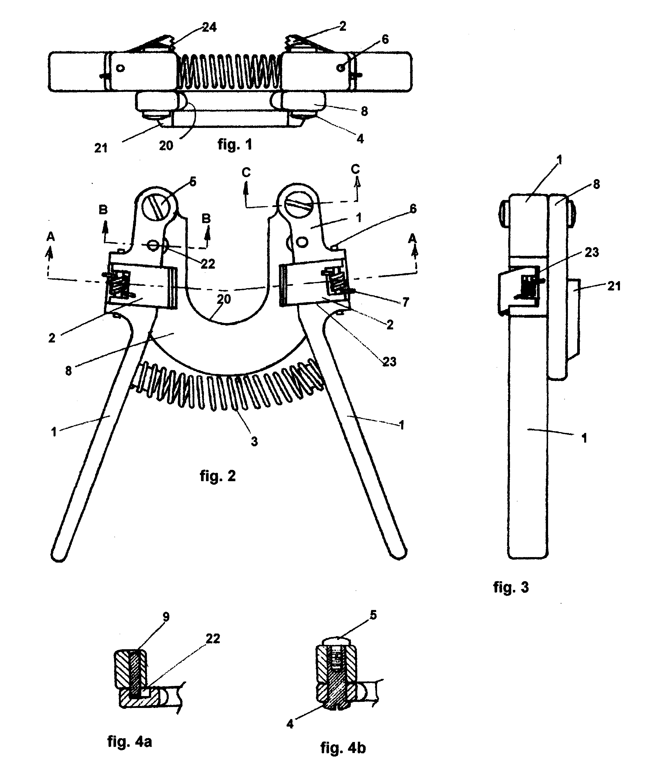
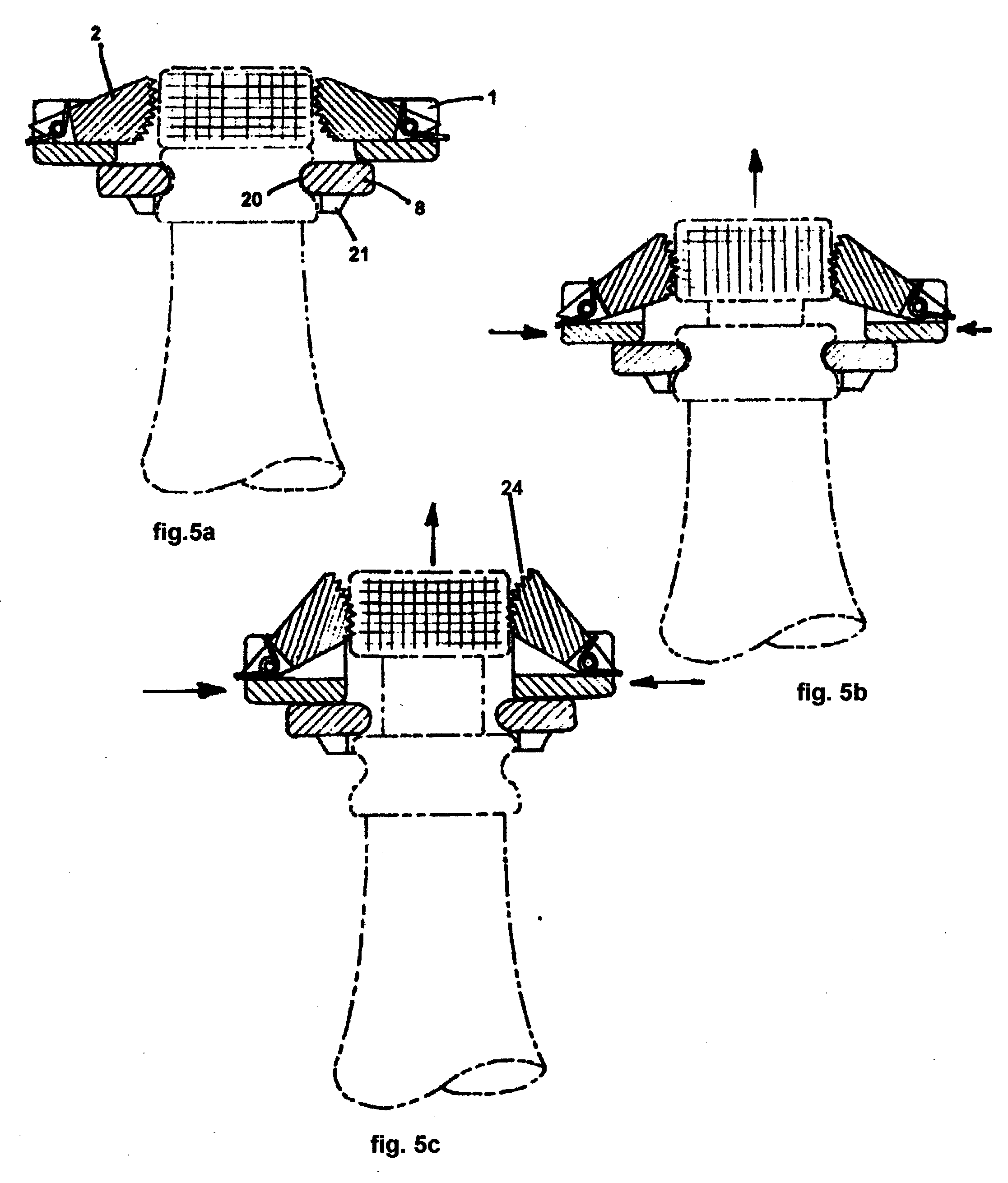
[0030] The preferred embodiment of this invention is illustrated in the three views of FIG. 1, FIG. 2, and FIG. 3. The lever-arms 1, shown in all three views, are connected to the base plate 8, by two pivots 4 These are kept in place by fillister head screws 5. The pivots 4, are a close but loose fit into the lever-arms 1, and of a length that allows free angular movement of the lever-arms. A compression spring 3, fitted between the lever-arms 1, tends to hold them apart. Stop-pins 9, protruding through the lever-arms into the stop-pin cavities 22 serve to constrain angular movement of the lever-arms to within the comfortable manipulation range of the average adult hand. Extractor links 2, are located in channels 23, formed across the lever-arms at a point in line with the center of the radius of the U-shaped cutout 20. Thus located, the extractor links 2, are moved toward the center of the U-shaped cutout 20, when lever-arms 1, are moved together.
[0031] The U-shaped cutout 20, of t...
PUM
Abstract
A hand tool with a U-shaped cutout to slide into the groove at the top of a champagne bottle, and pivoted lever-arms above the cutout straddling the stopper of the bottle. Extractor links connected to these lever-arms, are hinged at the outer end, and have teeth across the inner end, which is aligned with the stopper. Squeezing the lever-arms together causes the extractor links to engage and compress that part of the stopper exposed above the top of the bottle. The extractor links are angled upward toward the toothed end, so that the resulting combined upward force of the two links on opposite sides of the stopper, cause it to be extruded upward. Repeated actuations may be used to remove the stopper completely. The tool grips, and retains the stopper when completely closed.
Description
[0001] (Not applicable)FEDERALLY SPONSORED R&D[0002] (Not applicable)[0003] 1. Field of the Invention[0004] This invention relates to opening champagne bottles, and the like, by applying a force to the exposed part of the cork, or plastic, stopper.[0005] 2. Prior Art[0006] A number of devices have been patented to accomplish this task, most of which attempt to pry or pull the stopper out by exerting a force between the top of the bottle and the enlarged part of the cork, which is exposed. Simple lever systems such as those found in U.S. Pat. No. 4,598,613 Jul. 8, 1986 to Frederick W. Baum, U.S. Pat. No. 4,590,821 May 27, 1986 to James C. Olson, and U.S. Pat. No. 4,680,993 Jul. 21, 1987 to Jack M. Feliz, are examples of such devices. Geared lever systems are also used in some designs, such as found in U.S. Pat. No. 4,750,391 Jun. 14, 1988 to Stanley L. Sweath, and U.S. Pat. No. 4,947,711 Aug. 4, 1990 to Ben F. Glebeler. A cranked threaded shaft mated with a threaded tubular column ar...
Claims
Application Information
Patent Timeline
Application Date:The date an application was filed.
Publication Date:The date a patent or application was officially published.
First Publication Date:The earliest publication date of a patent with the same application number.
Issue Date:Publication date of the patent grant document.
PCT Entry Date:The Entry date of PCT National Phase.
Estimated Expiry Date:The statutory expiry date of a patent right according to the Patent Law, and it is the longest term of protection that the patent right can achieve without the termination of the patent right due to other reasons(Term extension factor has been taken into account ).
Invalid Date:Actual expiry date is based on effective date or publication date of legal transaction data of invalid patent.