Precise measuring device

a measuring device and precise technology, applied in the direction of mechanical measuring arrangement, instruments, using mechanical means, etc., can solve the problems of time-consuming setup and high system cos

Inactive Publication Date: 2004-05-06
COTNER TERRY L
View PDF17 Cites 27 Cited by
  • Summary
  • Abstract
  • Description
  • Claims
  • Application Information

AI Technical Summary

Problems solved by technology

This system is very expensive and requires time consuming setup prior to beginning work.

Method used


Image

  • Precise measuring device
  • Precise measuring device
  • Precise measuring device

Examples


Embodiment Construction

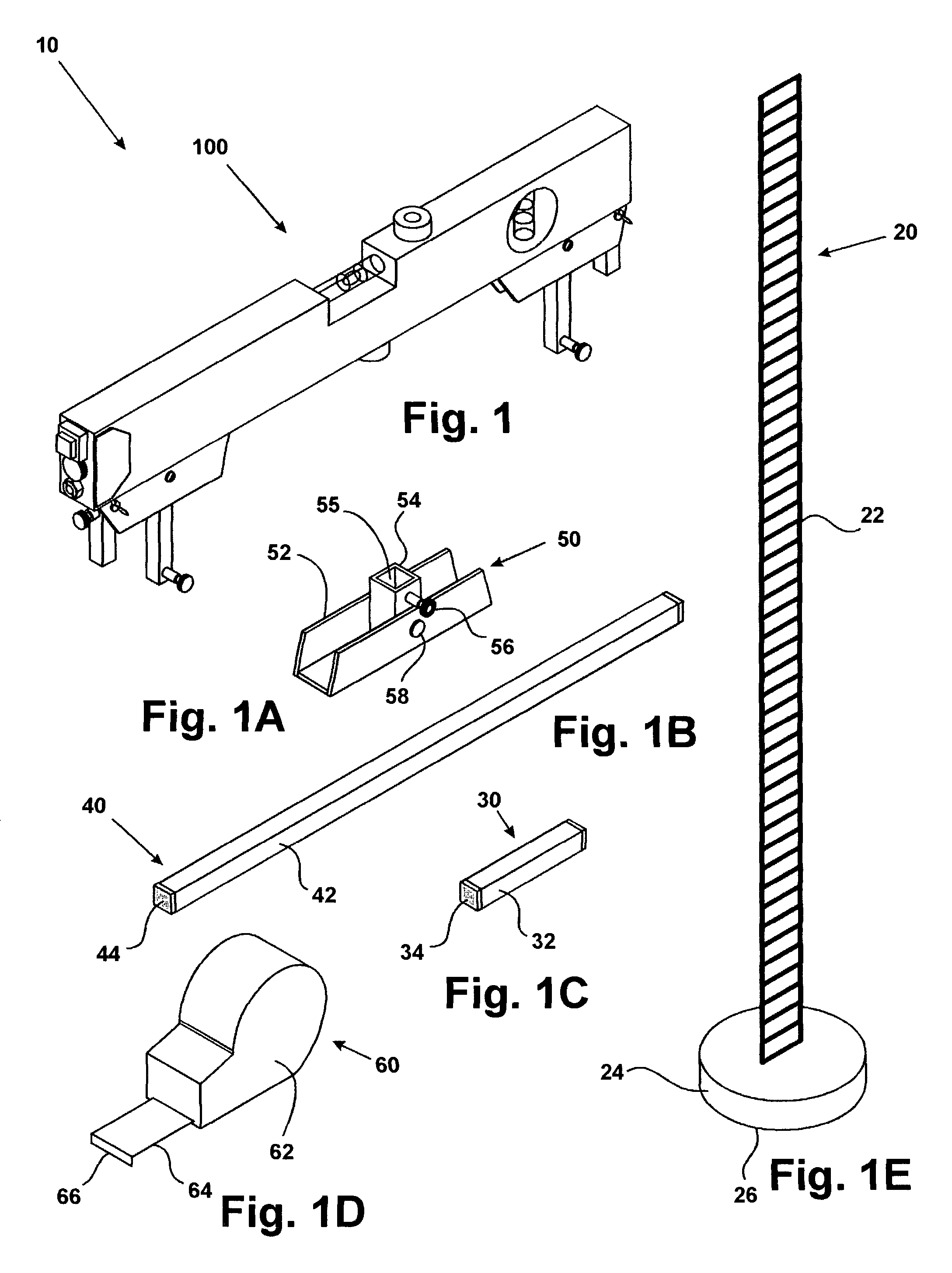
[0026] In accordance with the present invention, FIGS. 1 through 1E show perspective views of the complete invention, generally at 10. The six major sections of the present invention are free standing scale 20, small extension 30, for example of 3", a second longer extension 40 of for example 15", a stand assembly 50, tape measure 60, and laser level assembly 100.

[0027] Free standing scale 20 comprises a ruled surface 22, which may be made of metal, plastic, or other durable material and is marked in inches, centimeters, or any other system of measurement. Ruled surface 22 is affixed to magnetic base 24, which contains magnet 26. Magnet 26 provides weight to allow free standing scale 20 to stand firmly on a horizontal surface, in addition to allowing it to be affixed to any ferrous surface.

[0028] Small extension 30 comprises body 32, which is made of metal, plastic, or other durable material and is, for example 2" to 5" long, preferably 3", and plastic end caps 34.

[0029] A second lo...


PUM


Abstract

The present invention comprises a modified commercially available laser level, with a series of accessories to enable it to be used in a variety of usage configurations and orientations. The precise lazer tool includes at least one laser level assembly, at least two extensions, at least two base assemblies, at least one free standing magnetic scale, and a magnetic tape measure. The present invention is capable of establishing a datum line under the vehicle or other structure, along the sides, or other points remote from the frame. In addition, the present invention has means for placing it on a level surface. The present invention is also significantly less expensive than prior measuring devices.

Description

I FIELD OF THE INVENTION[0001] This invention relates to an improved measuring device.II BACKGROUND OF THE INVENTION[0002] In the event a vehicle is involved in an accident to the extent that its frame is damaged or deformed, it must be straightened prior to the performance of any body work. In a traditional repair shop, a device known as a ladder or rack system is employed to straighten a frame. This system is very expensive and requires time consuming setup prior to beginning work. Specific reference points need to be preset per the manufacturer's specifications before the damaged vehicle or structure is placed on the rack. Frame members which do not correspond to the rack's presets must then be forced back into shape. Alternatively, damaged frame members may be compared with undamaged members to determine the extent of damage. To this end, accurate measurements must be taken from undamaged portions of the frame and compared with the corresponding damaged areas.[0003] U.S. Pat. No...

Claims


Application Information

Patent Timeline
Patent Type & Authority Applications(United States)
IPC IPC(8): G01B3/10G01B5/00G01C15/00
CPCG01B5/0025G01C15/008G01C15/004G01B2003/1092G01B3/1092
Inventor COTNER, TERRY L.
Owner COTNER TERRY L
Why Eureka
Try Eureka