
Device, method and program for generating interpolation frame

a technology of interpolation frame and program, which is applied in the direction of color television with bandwidth reduction, instruments, television systems, etc., can solve the problem of not generating interpolation fram

Active Publication Date: 2004-05-27
RAKUTEN GRP INC
View PDF12 Cites 144 Cited by
  • Summary
  • Abstract
  • Description
  • Claims
  • Application Information

AI Technical Summary

Benefits of technology

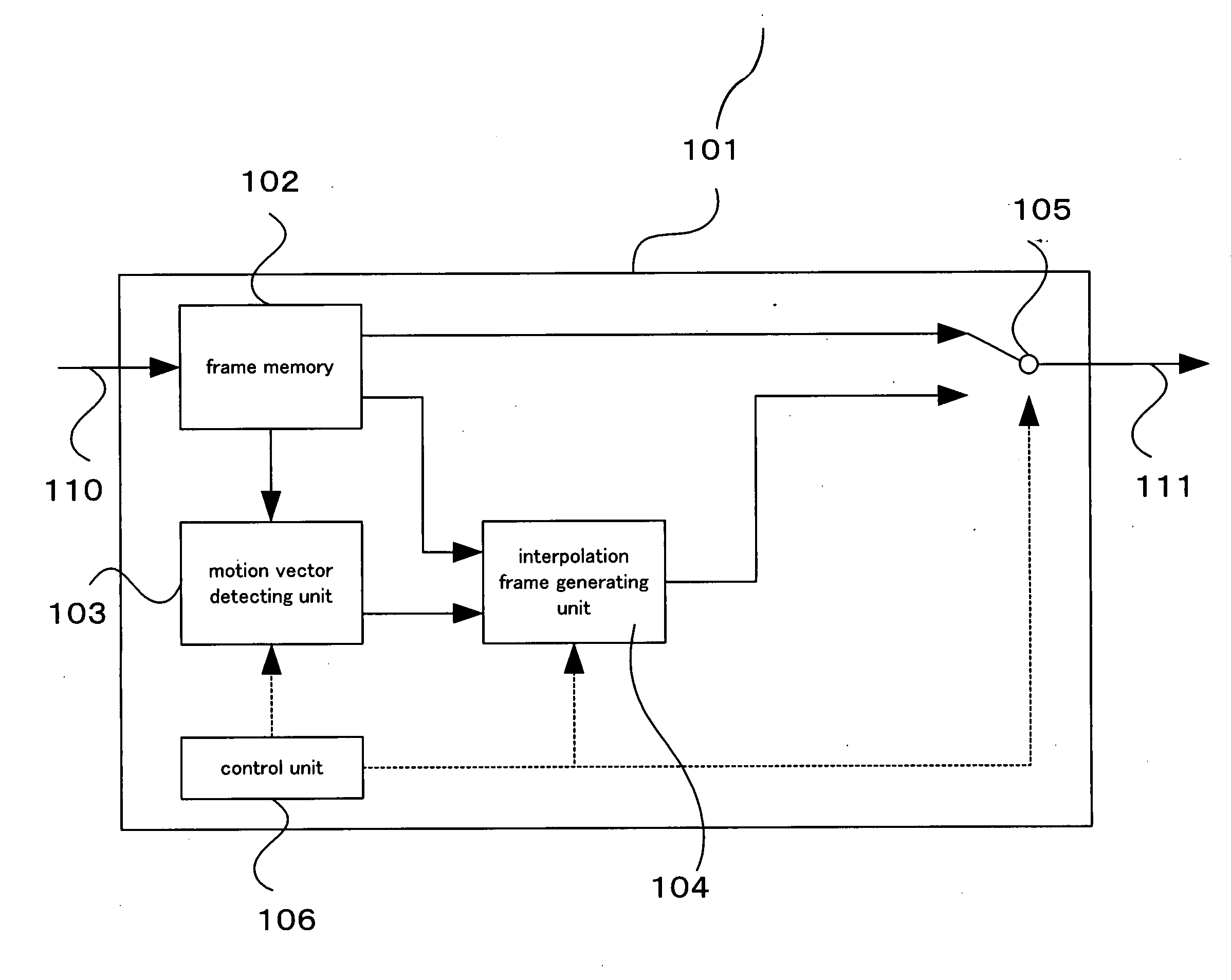
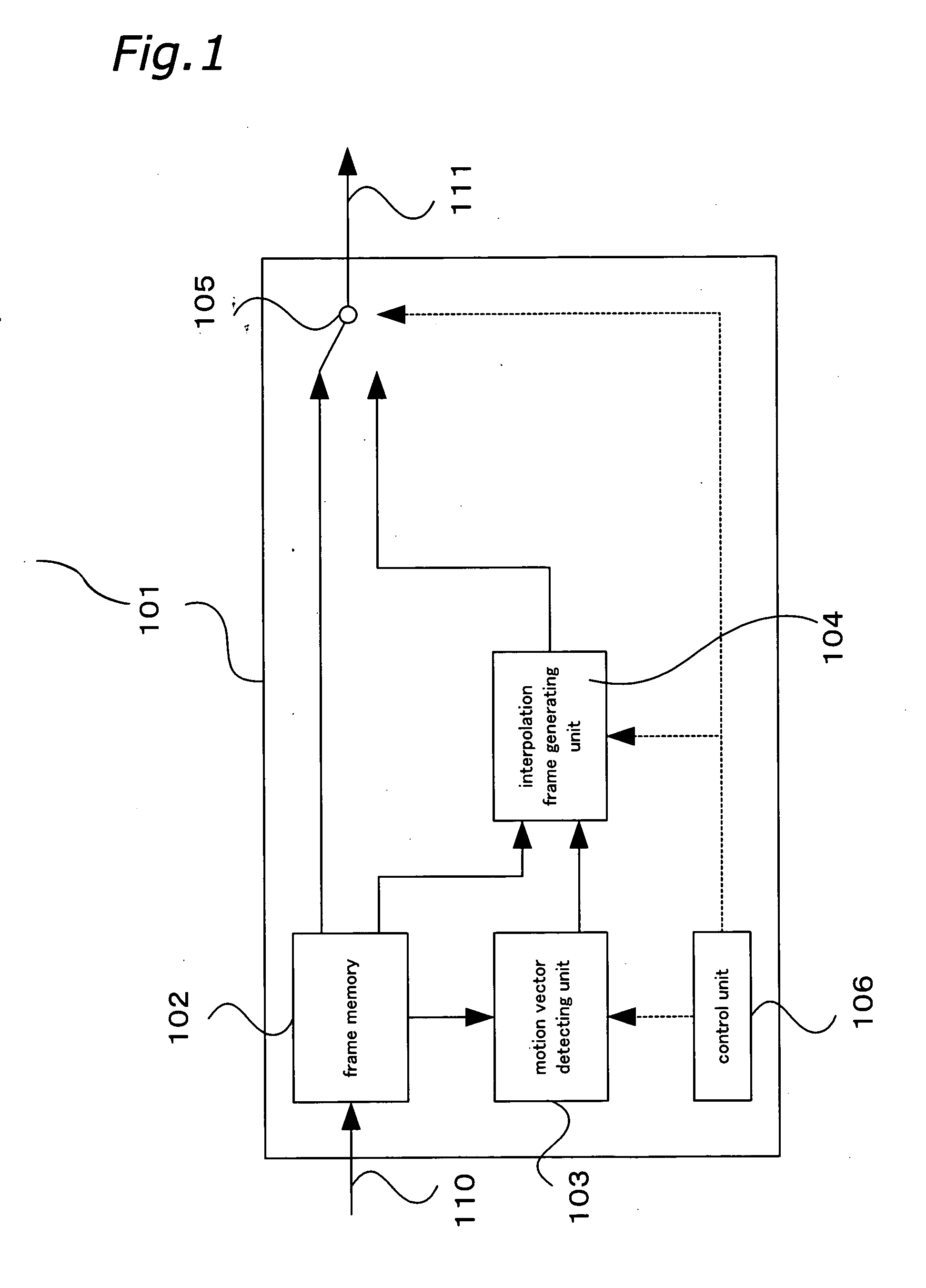
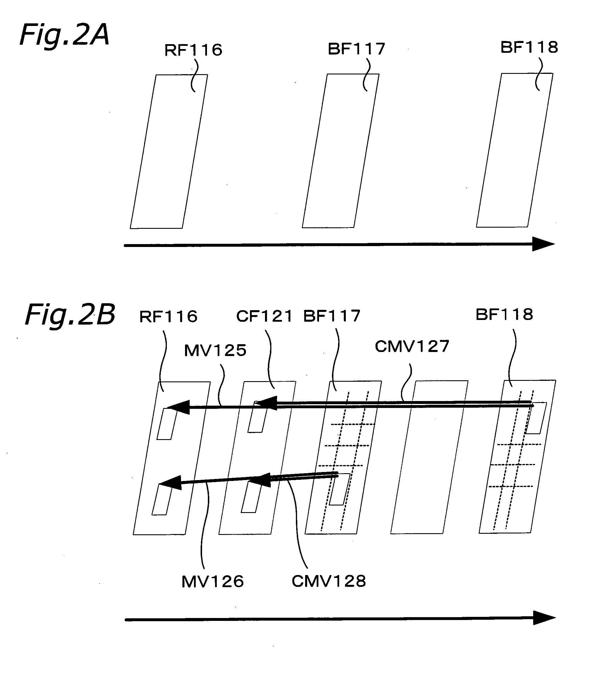
The present invention relates to an interpolation frame generation device, method, and program for generating an interpolation frame for interpolating image frames. The device uses motion compensation to generate the interpolation frame, which reduces the volume of data needed to transmit the image signals. The device includes a motion compensation vector acquisition unit, motion vector detection unit, and interpolation frame generation unit. The motion compensation vector acquisition unit acquires motion compensation vectors of coded blocks that form the coded image signal by decoding the coded image signal. The motion vector detection unit detects motion vectors between a base frame and a reference frame and detects the motion vector of an image block. The interpolation frame generation unit generates the interpolation frame based on the motion vectors of the image blocks. The invention improves the accuracy of interpolation frame generation and reduces the size of the circuit or device needed for the technique.

Problems solved by technology

In this interpolation frame generation device, if the image frame is not adequate for generating an interpolation frame, the interpolation frame is not generated.
The area determination step is for determining an interpolation inadequate area that is an outer frame area of an image frame and is not adequate for generating the interpolation frame.

Method used


Image

  • Device, method and program for generating interpolation frame
  • Device, method and program for generating interpolation frame
  • Device, method and program for generating interpolation frame

Examples


first embodiment

[0194] With reference to FIG. 4, the effects of the first embodiment will be described in detail. It is assumed that image frames 136-138 are obtained from the input image signal. The image frames 136-138 are images in which a car 141 traverses in front of a person 140. Here, in the image frame 137, the person 140 is hidden behind the car 141. In the conventional technique for generating an interpolation frame (a technique for detecting a motion vector in accordance with each image frame that is located before and after the interpolation frame in the display order), when generating an interpolation frame between the image frame 136 and the image frame 137 for example, the image frame 137 does not have data on the person 140, and thus appropriate motion vectors cannot be detected for the image block 142 that includes the person 140. On the other hand, in the technique of generating an interpolation frame according to the present invention, when generating an interpolation frame betwe...

second embodiment

[0265] [Second Embodiment]

[0266] A second embodiment of the present invention will be described with reference to FIGS. 15-20.

[0267] (1) Interpolation Frame Generation Device 201 FIG. 15 shows an interpolation frame generation device 201 according to the second embodiment of the present invention. The interpolation frame generation device 201 is provided in a television set, a personal computer (PC), a cellular phone or other devices that display image signals. The interpolation frame generation device 201 is a device that generates an interpolation frame for interpolating the image frames from the image frames that form a decoded image signal 212 that is obtained by decoding a coded image signal 210 that is coded by motion compensation using a decoding device 215.

[0268] Here, the motion compensation coding is aimed at reducing the temporal redundancy between image frames that form the image signal and compressing the information volume, and is performed by using motion compensation...

third embodiment

[0311] the present invention will be described with reference to FIGS. 21-24.

[0312] (1) Interpolation Frame Generation Device 601

[0313] FIG. 21 shows an interpolation frame generation device 601 for effectuating this function. The interpolation frame generation device 601 is provided in a television set, a personal computer (PC), a cellular phone or other devices that display an image signal. The interpolation frame generation device 601 is a device for generating an interpolation frame for interpolating image frames from image frames that form the decoded image signal 212 that is obtained by decoding the coded image signal 210 that is coded by motion compensation by the decoding device 215.

[0314] A difference between the interpolation frame generation device 601 and the interpolation frame generation device 201 that was shown in FIG. 15 is that the former does not have a function corresponding to the motion vector detecting unit 208. In addition, since operation of each unit that f...


PUM


Abstract

An interpolation frame generation device (201) that generates an interpolation frame that interpolates image frames that are obtained by decoding a coded image signal (210) that is coded by motion compensation, includes a motion vector deriving unit (203) and an interpolation frame generating unit (204). The motion vector deriving unit (203) acquires a motion compensation vector of a coded block that forms the coded image signal (210). The interpolation frame generating unit (204) generate the interpolation frame in accordance with the motion vector of the image block that forms an image frame by using the motion compensation vector of the coded block as the motion vector of the image block.

Description

[0001] 1. Field of the Invention[0002] The present invention-relates to an interpolation frame generation device, and more particularly to an interpolation frame generation device for generating an interpolation frame for interpolating image frames. The present invention further relates to a method for generating an interpolation frame and a program for generating an interpolation frame.[0003] 2. Description of the Prior Art[0004] An interpolation technique for a television set, a personal computer (PC), a cellular phone or. other devices that display an image signal, in which an interpolation frame for interpolating image frames is generated from image frames that form the image signal, and the generated interpolation frame is inserted between the image frames to be displayed, is well known in the prior art. This technique is used to smoothly display an image signal that is transmitted at a low frame rate in order to reduce the volume of the data, for example.[0005] FIG. 52 shows a...

Claims


Application Information

Patent Timeline
Patent Type & Authority Applications(United States)
IPC IPC(8): G06T9/00H04N7/01H04N7/50
CPCH04N7/014G06T9/004
Inventor SASAI, HISAOKONDO, SATOSHIKADONO, SHINYA
Owner RAKUTEN GRP INC
Learn More