
Vantilation and volume change measurements using permanent magnet and magnet sensor affixed to body

a technology of permanent magnet and sensor, applied in the field ofvantilation and volume change measurements using permanent magnet and magnet sensor affixed to body, can solve the problems of system interference, difficulty in adjusting, and failure to meet the needs of patients,

Inactive Publication Date: 2004-06-24
ALFRED E MANN INST FOR BIOMEDICAL ENG AT THE UNIV OF SOUTHERN +1
View PDF4 Cites 79 Cited by
  • Summary
  • Abstract
  • Description
  • Claims
  • Application Information

AI Technical Summary

Problems solved by technology

These efforts, however, may not be wholly satisfactory.
This can be particularly problematic in applications requiring changes to be measured over a long period, such as during sleep or exercise.
These systems can also be subject to interference from stray magnetic fields.
Systems that measure circumferential changes in the chest (e.g., U.S. Pat. No. 4,815,473) can also be subject to artifacts caused by deformation of the soft tissue.
Some of these systems, moreover, can be complex and bulky.
This system, however, can restrict the mobility of the human subject and be subject to errors due to movement of the subject.

Method used


Image

  • Vantilation and volume change measurements using permanent magnet and magnet sensor affixed to body
  • Vantilation and volume change measurements using permanent magnet and magnet sensor affixed to body
  • Vantilation and volume change measurements using permanent magnet and magnet sensor affixed to body

Examples


Embodiment Construction

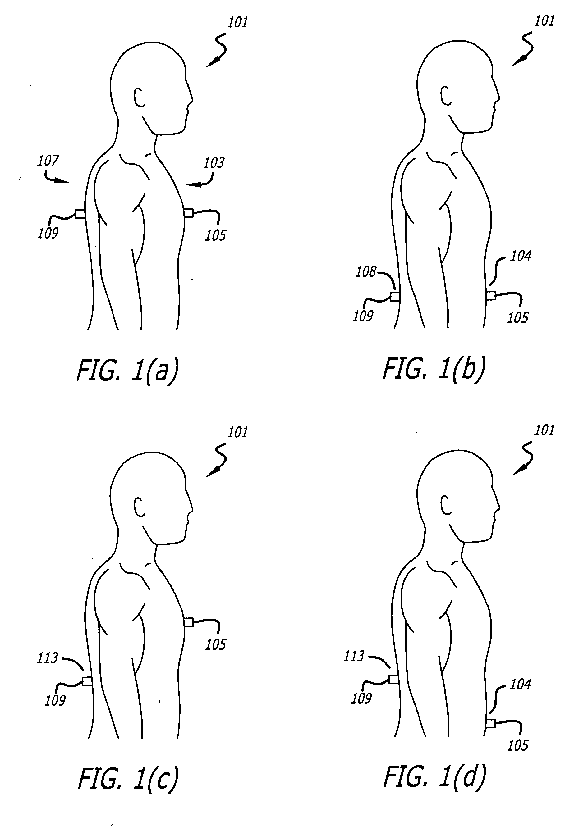
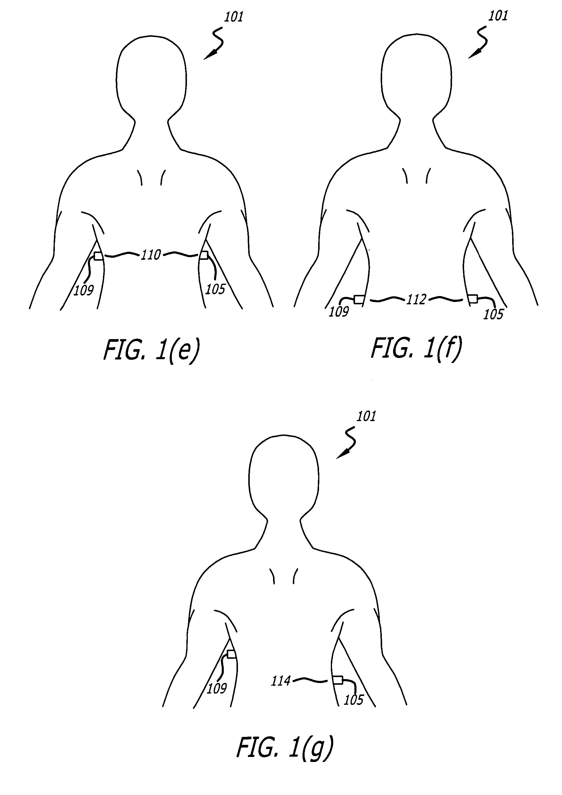
[0051] FIGS. 1(a)-1(g) illustrate a permanent magnet and a magnet sensor affixed to different locations on a surface of a body that moves in response to ventilation.

[0052] As shown in FIG. 1(a), a human subject 101 has a chest 103 to which a magnet 105 may be affixed. The human subject 101 also has an upper back 107 to which a sensor 109 may be affixed.

[0053] As is well known, the chest 103 and upper back 107 are parts of a surface, i.e., the upper torso, that moves in response to ventilation by the subject 101. The chest 103 and the upper back 107 typically move apart from one another during inhalation and toward one another during exhalation.

[0054] The magnet 105 may be a permanent magnet. It may be made from the rare earth samarium cobalt or from neodymium. It may also be made from any other type of material or combination of materials.

[0055] The sensor 109 may be a magnetic sensor. It may be a magnetoresistive device, including an anisotropic or giant magnetoresistive device. It...


PUM


Abstract

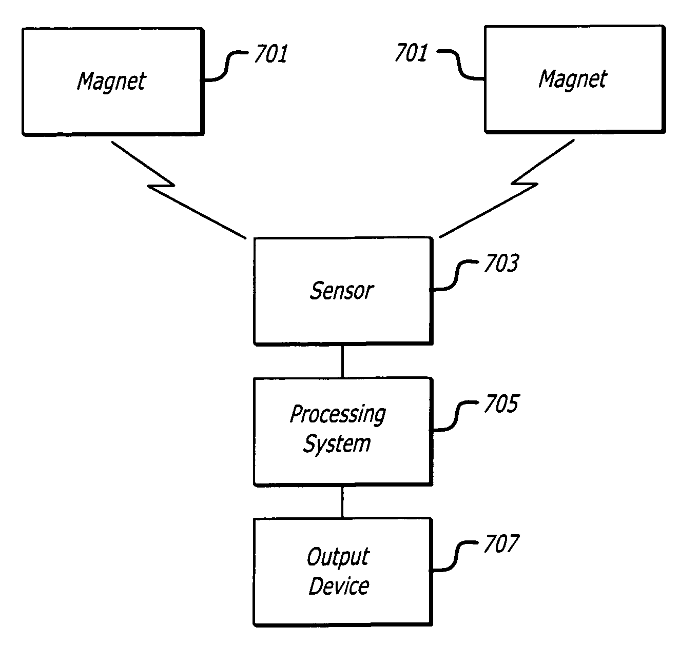
Apparatus for measuring ventilation of a body having a surface that moves in response to the ventilation. The apparatus may include a first permanent magnet, a first magnet attachment mechanism configured to attach the first magnet to the surface, a first magnetic sensor having an output, a first sensor attachment mechanism configured to attach the first sensor to the surface, and a processing system configured to communicate with the magnetic sensor and to determine the ventilation based on the output of the magnetic sensor. An associated process is also disclosed, along with broader applications of the apparatus and process.

Description

[0001] This application is related and claims priority to U.S. provisional application serial No. 60 / 412,129, filed Sep. 19, 2003, entitled "Non-intrusive Measurement of Ventilation and Body Volume Changes By Magnetic Plethysmography," the entire content of which is incorporated herein by reference.[0002] 1. Field[0003] This application relates to the measurement of ventilation, as well as to the measurement of volume changes in body parts.[0004] 2. Related Art[0005] The measurement or detect of ventilation, such as the respiration of a human subject, is often necessary or desirable. Performing this task in a non-intrusive manner and without the use of a mouthpiece or mask is also often necessary or desired.[0006] Efforts have been made to address this need by measuring changes in the volume of the lung and / or the abdomen by monitoring movement of the rib cage and / or abdominal wall. These efforts, however, may not be wholly satisfactory.[0007] Systems that use coils (e.g., U.S. Pat....

Claims


Application Information

Patent Timeline
IPC IPC(8): A61B5/0205A61B5/091A61B5/113
CPCA61B5/0205A61B5/4818A61B5/1135A61B5/091
Inventor YAMASHIRO, STANLEY M.
Owner ALFRED E MANN INST FOR BIOMEDICAL ENG AT THE UNIV OF SOUTHERN
Learn More