Pipe wrench retrofit

a technology of pipe wrenches and wrenches, applied in the field of adjustable pipe wrenches, can solve the problem that the nut must be turned a number

Active Publication Date: 2004-07-08
GREGORY N SCOTT
View PDF14 Cites 9 Cited by
  • Summary
  • Abstract
  • Description
  • Claims
  • Application Information

AI Technical Summary

Benefits of technology

0008] The present invention overcomes the deficiencies of the prior art by providing a modified nut assembly and locking assembly. In an embodiment of the present invention, a nut assembly for use on a wrench includes a nut for engaging and disengaging the shank of the wrench and a spring for biasing

Problems solved by technology

A problem realized by this arrangement is that the nut must be

Method used


Image

  • Pipe wrench retrofit
  • Pipe wrench retrofit
  • Pipe wrench retrofit

Examples


Embodiment Construction

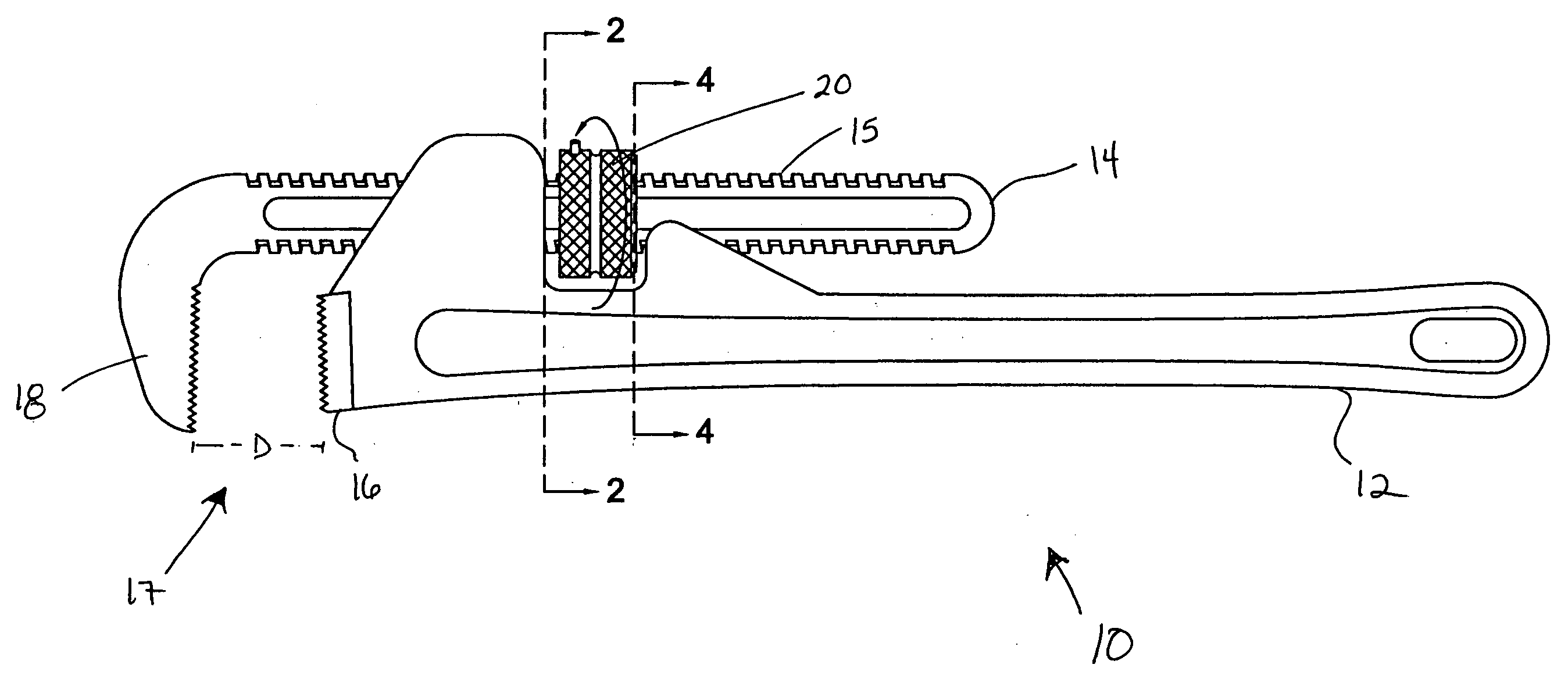
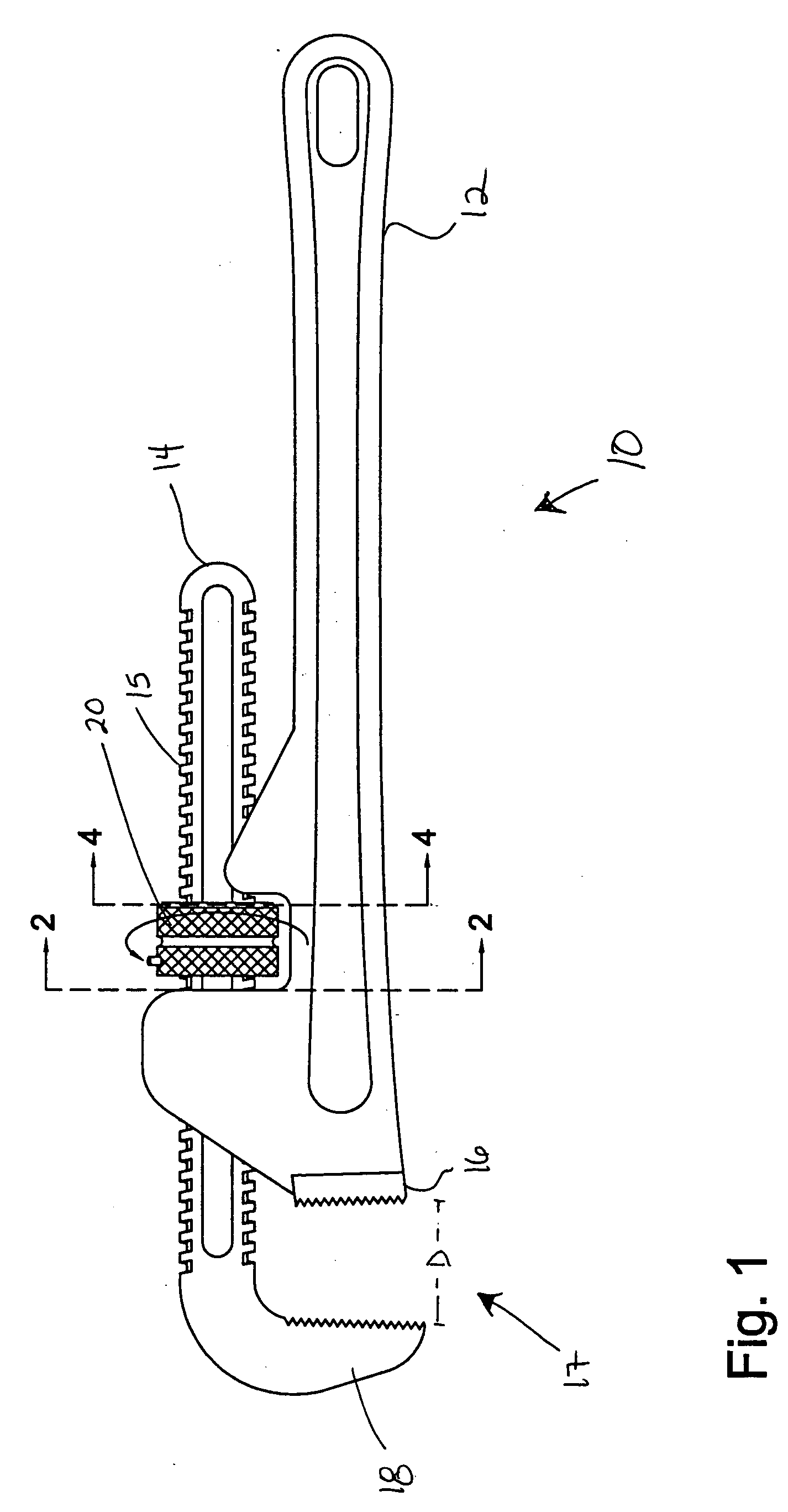
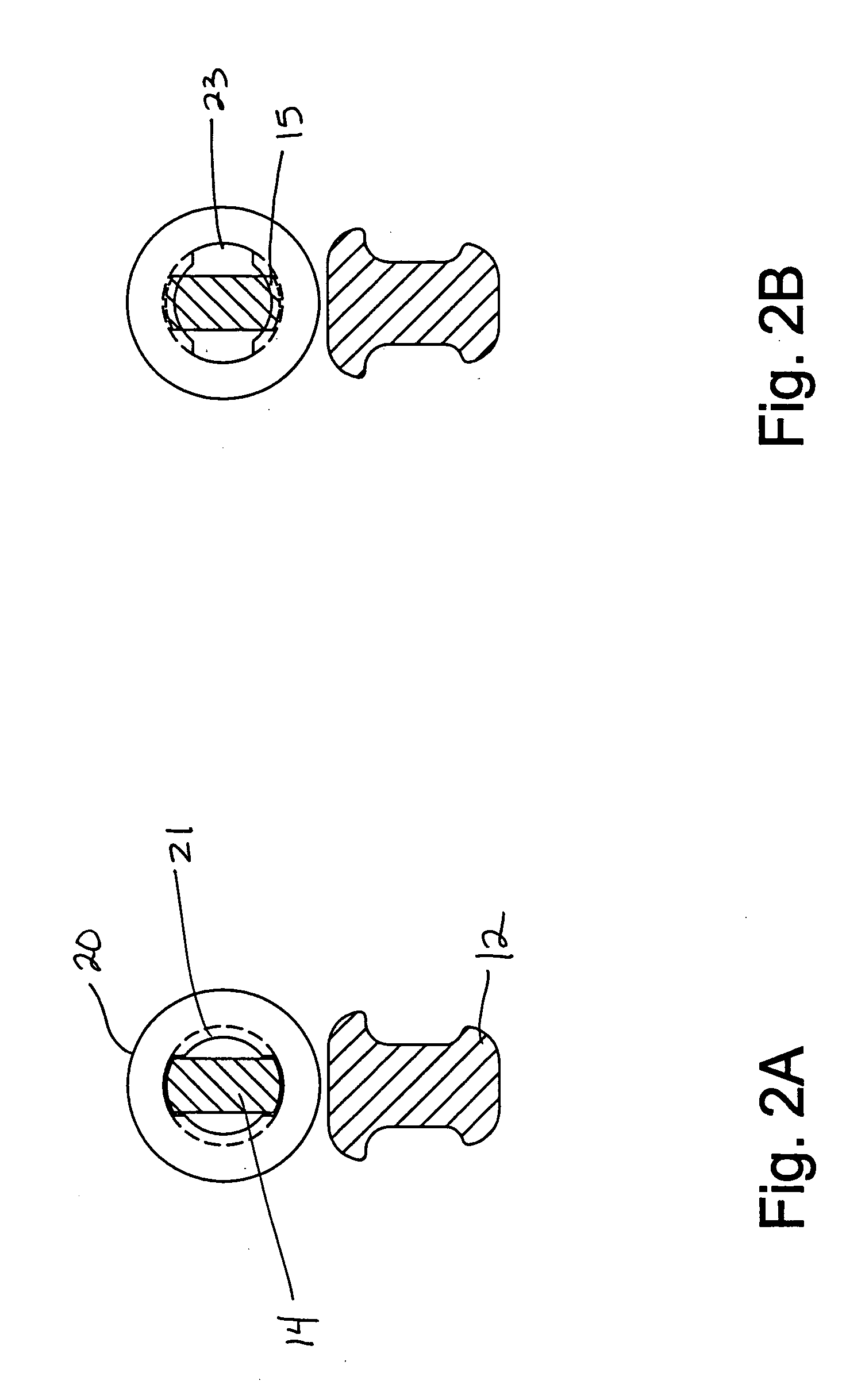
[0008] The present invention overcomes the deficiencies of the prior art by providing a modified nut assembly and locking assembly. In an embodiment of the present invention, a nut assembly for use on a wrench includes a nut for engaging and disengaging the shank of the wrench and a spring for biasing the nut to a position where the shank of the wrench is locked in place. Threads internal to the nut matingly engage threads on the shank of the wrench when in a locked position, and grooves internal to the nut allow the shank of the wrench to slide freely through the nut when in an unlocked position.

[0009] In another embodiment, a locking assembly for use on a wrench includes a housing, a sliding portion, a locking portion, and a spring. The sliding portion and locking portion preferably abut each other within the housing. The spring is preferably located in the sliding portion and extends from the sliding portion to the shank of the wrench.

BRIEF DESCRIPTION OF THE DRAWINGS

[0010] For a...


PUM


Abstract

The specification discloses a modified nut assembly and locking assembly for locking the shank of a wrench in place. The nut assembly preferably includes a nut for engaging and disengaging the shank of the wrench and a spring for biasing the nut to a position where the shank of the wrench is locked in place. Threads internal to the nut matingly engage threads on the shank of the wrench when in a locked position, and grooves internal to the nut allow the shank of the wrench to slide freely through the nut when in an unlocked position. The locking assembly preferably includes a housing, a sliding portion, a locking portion, and a spring. The sliding portion and locking portion preferably abut each other within the housing. The spring is preferably located in the sliding portion and extends from the sliding portion to the shank of the wrench.

Description

CROSS-REFERENCE TO RELATED APPLICATIONS[0001] This application claims the benefit of provisional application Serial No. 60 / 413,929 filed on Sep. 26, 2002, which is incorporated by reference herein as if reproduced in full below.STATEMENT REGARDING FEDERALLY SPONSORED RESEARCH OR DEVELOPMENT[0002] Not Applicable.BACKGROUND OF THE INVENTION[0003] 1. Field of the Invention[0004] The present invention relates to an adjustable pipe wrench. More precisely, the present invention relates to a modified nut assembly and locking assembly for use on an adjustable pipe wrench.[0005] 2. Background of Relevant Art[0006] Conventionally, when securing a pipe wrench to a pipe or rod, a nut that is capable of adjusting the size of the mouth of the pipe wrench is turned so that the mouth of the wrench is opened large enough to receive the pipe or rod. The pipe or rod is inserted into the mouth of the wrench, and then, the mouth of the pipe wrench is tightened to the pipe or rod by turning the nut in th...

Claims


Application Information

Patent Timeline
IPC IPC(8): B25B13/50
CPCB25B13/5058
Inventor GREGORY, N. SCOTT
Owner GREGORY N SCOTT
Why Eureka
Try Eureka