External fixation device for reducing bone fractures

a fixation device and bone fracture technology, applied in the field of external fixation devices for reducing bone fractures, can solve the problems of reference marks, state-of-the-art fixation devices that cannot meet the above demands, and inconvenient use,

Inactive Publication Date: 2004-07-08
ORTHOFIX SRL
View PDF8 Cites 72 Cited by
  • Summary
  • Abstract
  • Description
  • Claims
  • Application Information

AI Technical Summary

Benefits of technology

0023] The technical problem is solved according to the invention by an external fixation device as previously indicated and as defined in the characterizing portion of claim 1 and followings.

Problems solved by technology

Unfortunately, state-of-art fixation devices come short of filling the above demands in that they are made of a homogeneous structure, usually of a plastic material transparent to X-radiation to permit unobstructed radiographs of the fractured region.
Thus, the outward appearance of such fixation devices is often so unsightly that they are hidden under some covering.
However, a reference mark as above can be easily altered for instance by repeated sterilisation of the device in steam autoclaves or can chip away due to occasional impacts during use of the device.
However, none of the above documents of the prior art from U.S. Pat. No. 6,030,386 to EP 0807419 disclose or suggest providing identifiable means on external fixation devices as defined above, which would assist the orthopaedist in his / her work connected to the use of those devices.

Method used


Image

  • External fixation device for reducing bone fractures
  • External fixation device for reducing bone fractures
  • External fixation device for reducing bone fractures

Examples


Embodiment Construction

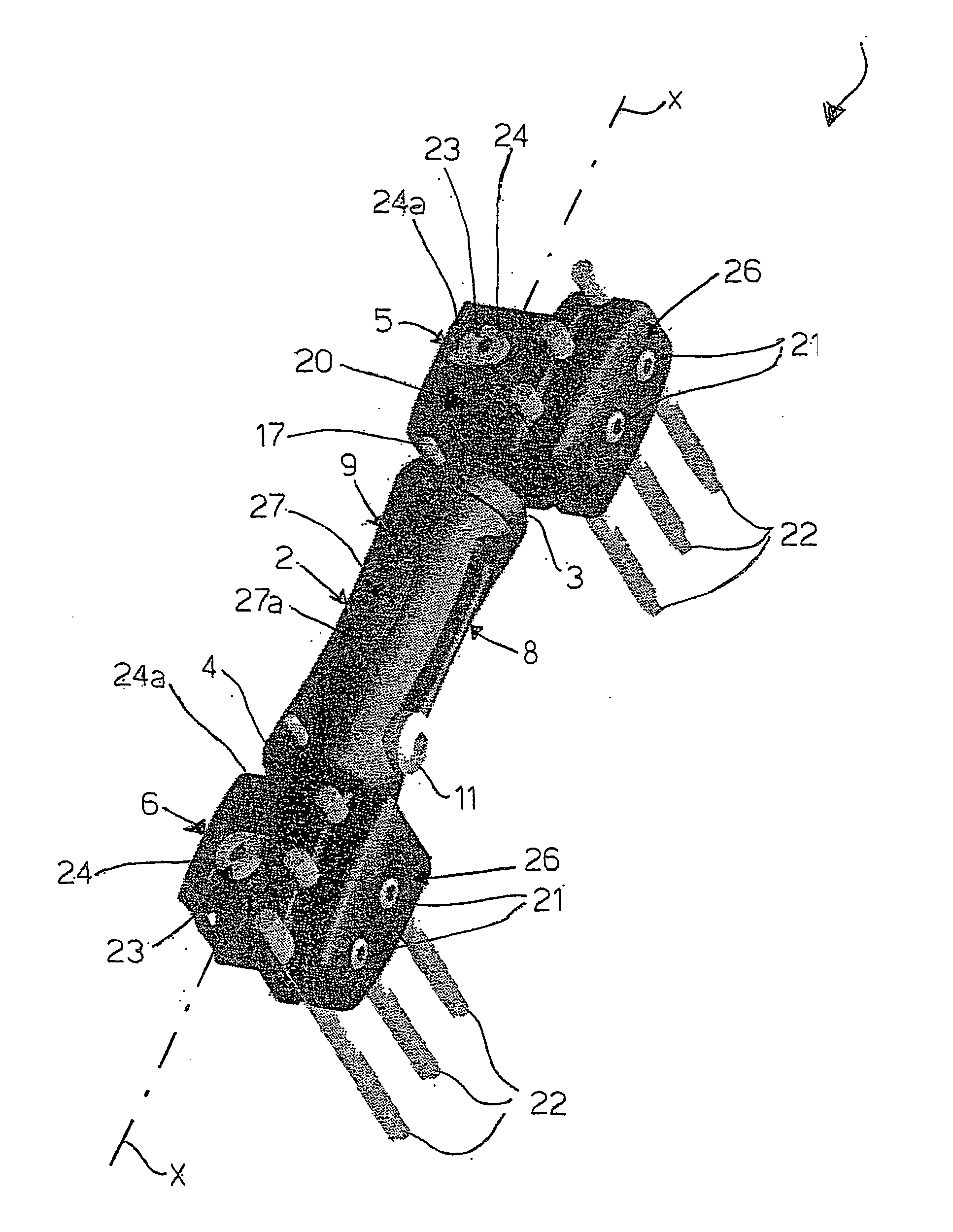
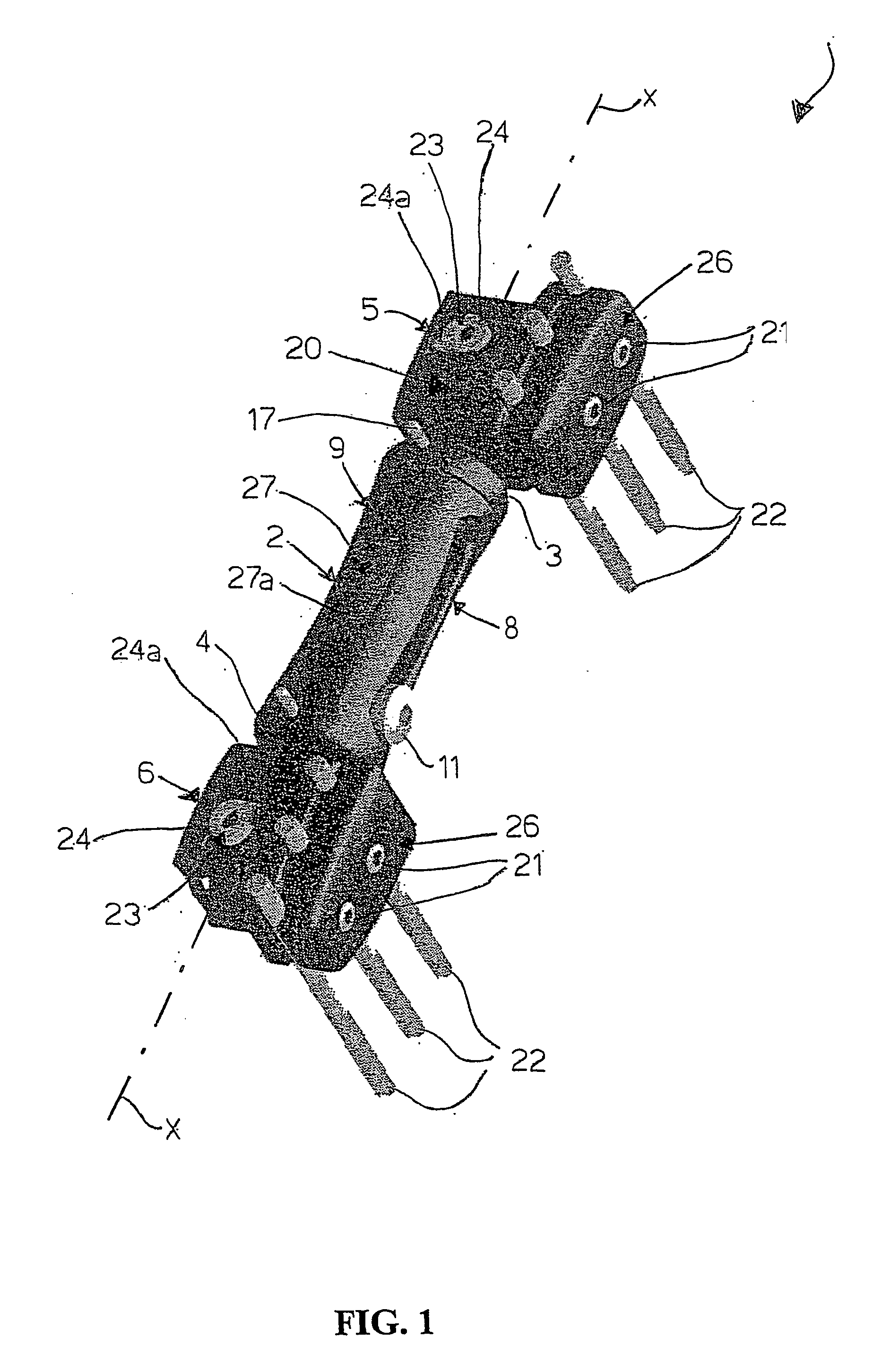
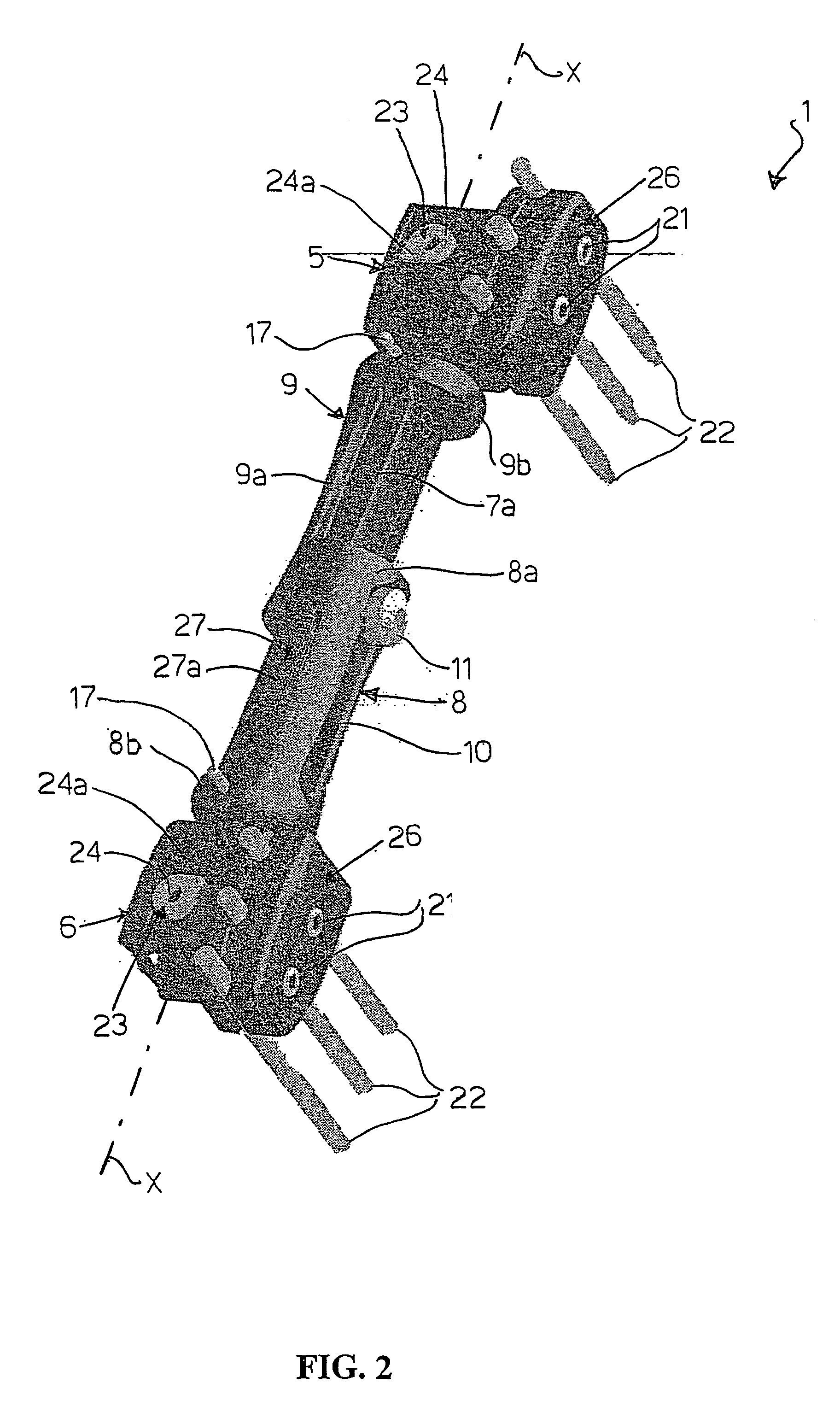
[0035] With reference to annexed FIGS. 1 to 6, a unilateral axial external fixation device for reducing bone fractures in orthopedic surgery, according to this invention, is shown generally at 1.

[0036] The fixation device 1 has a carrying structure made up of interconnected elements, which structure comprises a rod-like central body 2 having a longitudinal axis x-x, and having opposite ends 3, 4 which are articulated to respective clamps 5, 6 for bone screws.

[0037] The rod-like central body 2 and clamps 5, 6 are preferably made up of a material transparent to X-radiation, such as a polyetherketone plastics matrix, known as "Peek", suitably reinforced with a predetermined amount of carbon fibers to confer a suitable rigidity.

[0038] The rod-like central body 2 is axially extendible and comprises a first part 8 and a second part 9 slidably coupled to each other together to allow the central body 2 to be extended telescopically.

[0039] Said parts 8, 9 comprise each a first portion 8a, 9a...


PUM


Abstract

The invention relates to a novel type of an external fixation device having a carrying structure (1; 40) of interconnected elements (2, 5, 6) comprising an extendible central body (2), and clamps (5, 6) for bone screws respectively articulated on opposed ends (3, 4) of the central body (2), said central body comprising two parts (8, 9) telescoping slidable one on the other, each of said parts (8, 9) including a first portion (8a; 9a) of elongate shape formed integrally with a second end portion (8b; 9b) of substantially cylindrical shape, said first portions (8a, 9a) of the parts (8, 9) being slidably coupled to each other by means of a driving groove (7) formed longitudinally in one the first portion (8a) and a corresponding slide (7a) formed longitudinally in the other first portion (9a) and means being provided in said parts (8, 9) for stopping their sliding movement characterized in that it further comprises at least one plate (27; 41; 42; 43; 60) having predetermined contour shape and thickness, at least one recess (28; 44; 47; 51) formed on the surface of at least one of the interconnected elements (2, 5, 6) and having its contour shape matching the contour shape of said at least one plate (27; 41; 42; 43; 60), and means (30, 31; 46, 46a; 49, 50 53, 54) for releasably securing said at least one plate (27; 41; 42; 43; 60) in said at least one recess (28; 44; 47; 51).

Description

[0001] This invention broadly relates to an external fixation device for reducing bone fractures in orthopedic surgery.[0002] More particularly, the invention relates to an external fixation device having a carrying structure made up of interconnected elements, specifically a structure comprising an extendible central body and oppositely located clamps for bone screws, which clamps are articulated to respective ends of the central body by means of ball joints.[0003] In this specific technical field, external fixation devices have long been employed to foster recovery of bone fractures by holding the bone fragments firmly in place.[0004] Such external fixation devices comprise a central body of substantially cylindrical shape, which is extendible axially and has bone screw clamps articulated to its opposed ends by means of ball joints. The clamps are connected to rod-like bone screws which have been implanted into the cortex of the broken bone, from either sides of the fracture. Usua...

Claims


Application Information

Patent Timeline
Patent Type & Authority Applications(United States)
IPC IPC(8): A61B17/60A61B17/64A61B90/92A61B90/94
CPCA61B17/6458A61B2019/446A61B2019/444A61B19/44A61B90/90A61B90/92A61B90/94
Inventor COATI, MICHELEROSSI, LUIGI
Owner ORTHOFIX SRL
Why Eureka
Try Eureka