Long bone fracture traction reduction navigation apparatus

A navigation device and traction reduction technology, applied in fractures, medical science, surgery, etc., can solve problems such as difficult three-dimensional geometric shape reduction, complex shape of long bones, and affecting surgical effects, etc., to achieve convenient image acquisition, accurate surgery, and improved reduction. The effect of precision

Inactive Publication Date: 2008-12-31
BEIHANG UNIV
View PDF0 Cites 41 Cited by
  • Summary
  • Abstract
  • Description
  • Claims
  • Application Information

AI Technical Summary

Benefits of technology

This technology helps reduce pain caused by broken or damaged parts of longer bones called femurs when they heal from injury. It uses an optically tracked camera that captures data about these areas while still being able to see them clearly through lenses attached to cameras. These imaging techniques help medical professionals accurately locate where their damage has been located without exposing themselves to harmful rays like x-rays.

Problems solved by technology

Technics: In this type of treatment for long bony fracture patients, reducing tension with external devices can help reduce pain or improve healing outcomes by allowing the patient's body to move back into its normal position before being fixed permanently. However, current methods are limited because they require multiple x- ray exposing sessions at different locations on the subject's skin surface while also requiring manual adjustment steps from outside the procedure itself due to lack of accurate 3 - dimensional measurement tools.

Method used


Image

  • Long bone fracture traction reduction navigation apparatus
  • Long bone fracture traction reduction navigation apparatus
  • Long bone fracture traction reduction navigation apparatus

Examples


Embodiment Construction

[0062] The present invention will be further described in detail below in conjunction with the accompanying drawings.

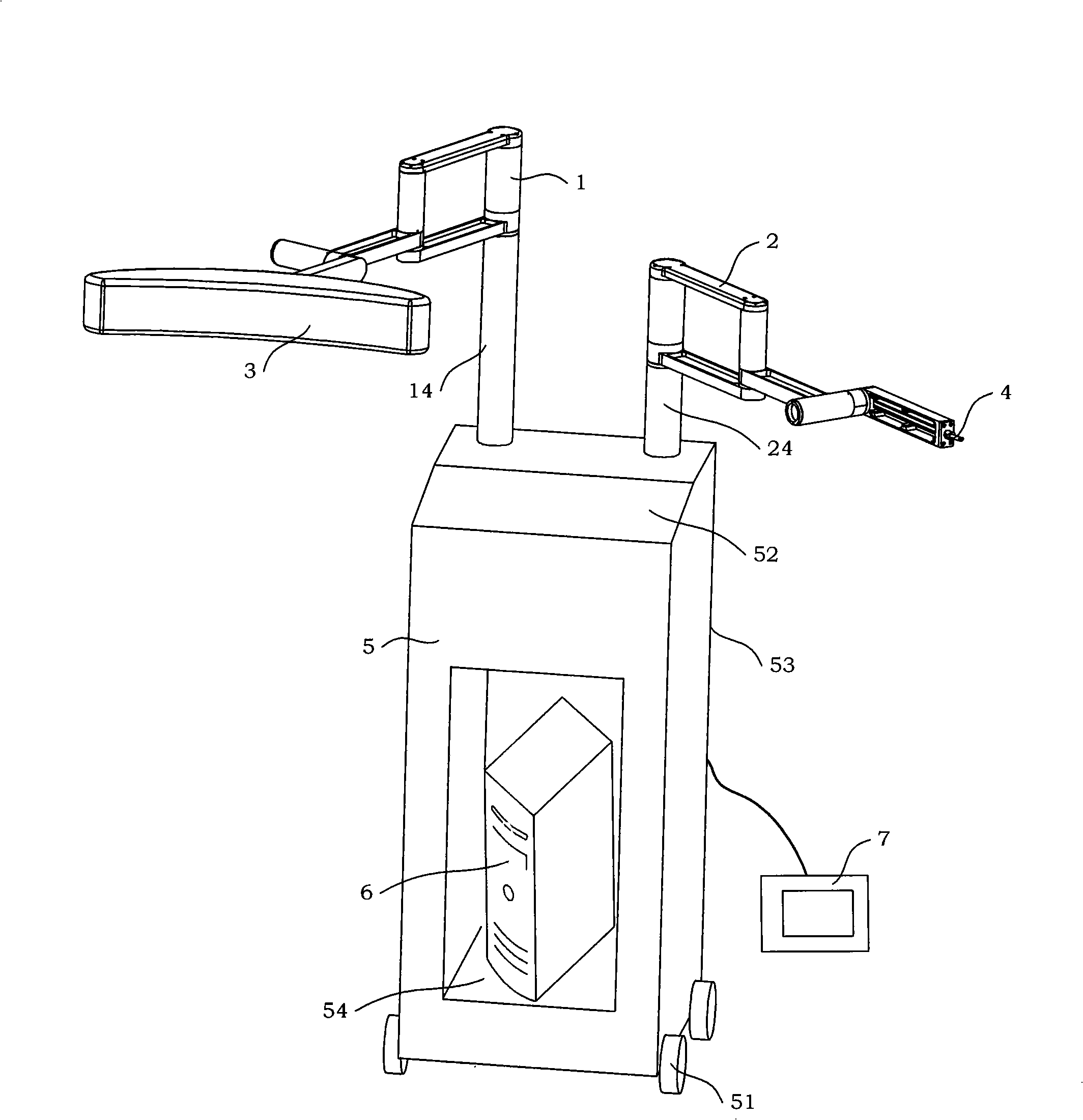
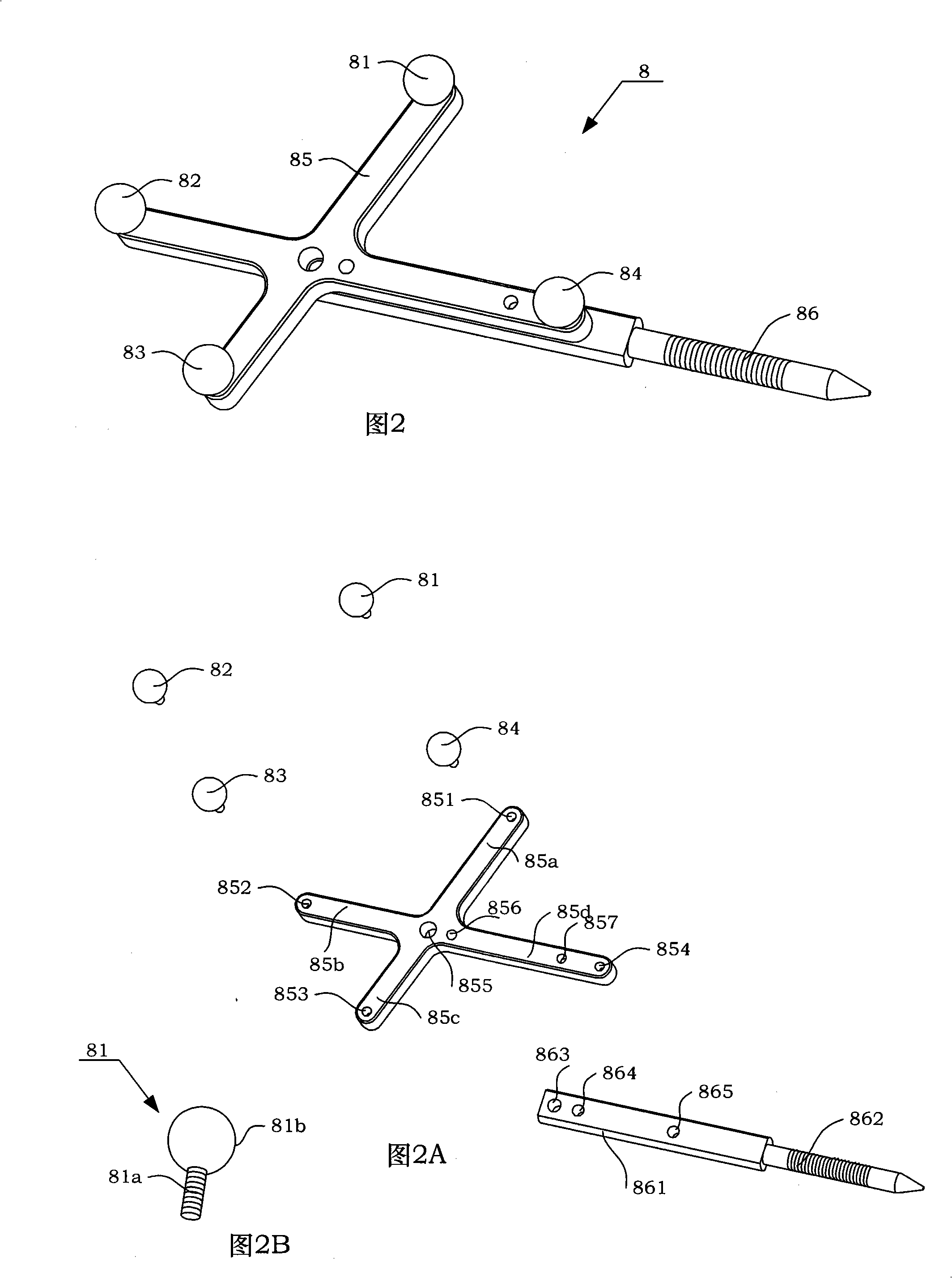
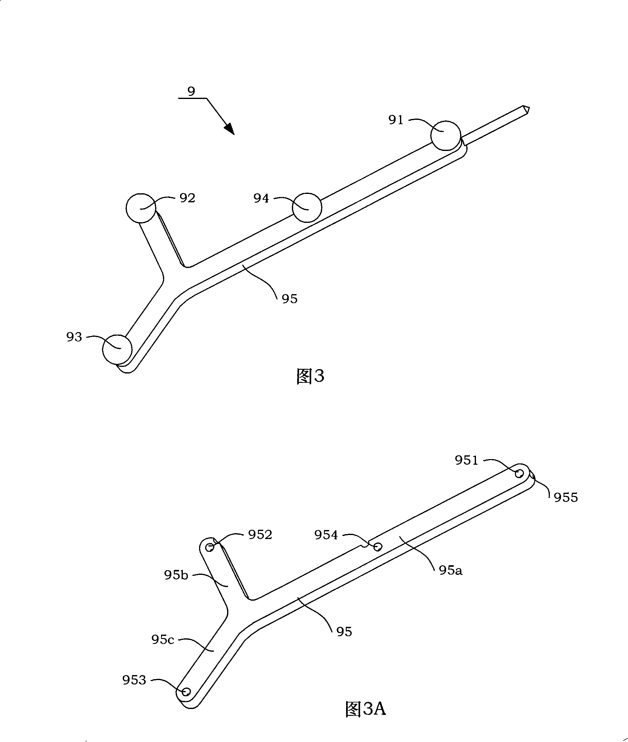
[0063] see figure 1 As shown, a kind of traction reduction navigation device applicable to long bone fractures of the present invention consists of a first mechanical arm 1, a second mechanical arm 2, a mobile vehicle 5, a pedal 7, a photoelectric tracker 3, an end effector 4, a tracking The marker component 8 and the spatial point collector 9 are composed; the tracking marker component 8 is installed at the fracture of the long bone, and is used to determine the spatial coordinates of the fracture of the long bone, and at the same time mark out the lesion information points at the fracture; the spatial point collector 9 is held by the doctor In the hand, it is used to collect the position data of the feature point represented by the reflective ball of the tracking marker assembly 8 in the clinical operating environment. Wherein, the first mechanical arm 1 a...


PUM


Abstract

The invention discloses a fracture traction reduction guiding device of a long bone. The device comprises a driving mechanical arm, a driven mechanical arm, a photoelectric tracer, an end effector, a trolley, a tracking mark component and a spatial point acquisition unit. The tracking mark component is installed on the fracture position of the long bone. The spatial point acquisition unit is held by a doctor. A prop A of the driving mechanical arm and a prop B of the driven mechanical arm are installed on the upper panel of the shell of the trolley respectively. The photoelectric tracer is installed on the end cover of a rocker A of the driving mechanical arm. The end effector is installed on the end cover of a rocker B of the driven mechanical arm. A computer system is arranged in the wagon box of the trolley. The driving mechanical arm has the same structure with the driven mechanical arm. The fracture traction resetting guiding device of the long bone can assist the doctor to finish the reduction operation of 3D geometry of a wounded limb and the mechanical arm is used for fixing the distant end of the wounded limb to improve the accuracy of reduction and to reduce the radiation of X-ray. The tracking mark component is arranged on the fractured bone that needs to be operated, so the position of a characteristic point marked by the tracking mark component is easier to be tracked by the photoelectric tracer.

Description


Claims


Application Information

Patent Timeline
Owner BEIHANG UNIV
Why Eureka
Try Eureka