Bone plate

a bone plate and plate body technology, applied in the field of bone plates, can solve the problems of loosening of the angular relationship between the bone plate and the compression screw, and limited ability of the locking screw to compress bone fragments, so as to facilitate both bone reduction and bone plate stabilization, and prevent movement of the bone pla

Active Publication Date: 2016-10-18
CARDINAL HEALTH 247 INC
View PDF326 Cites 43 Cited by
  • Summary
  • Abstract
  • Description
  • Claims
  • Application Information

AI Technical Summary

Benefits of technology

[0001]Bone plates are used to provide structural support for fixation of various types of bone fractures. Bone plates are generally constructed of metal, e.g., titanium, and may be fabricated in a number of different shapes and sizes to conform to different types of bone for use with different types of fractures. In operation, bone plates are secured to the bone to “reduce” the fracture, i.e., bring bone fragments into alignment and close proximity to facilitate the body's natural bone growth and healing. Bone reduction is generally accomplished using compression screws. Compression screws have threaded shafts and are anchored through holes in the bone plate and into the various bone fragments, which upon tightening pull the bone fragments together under a compression load against the plate. However, due to dynamic loading caused by physiological movement, the angular relationship between the bone plate and the compression screws may loosen over time.
[0002]Securing or locking screws may be anchored both to the bone plate and to the bone to provide a fixed angular relationship between the bone plate and the locking screws, which reduces the incidence of loosening. A locking screw has a threaded head, which mates with corresponding threads of a threaded hole in the bone plate, and a threaded shaft, which anchors to the bone. Thus, as a locking screw is secured to both the bone and the bone plate, movement between the bone plate and the locking screws is reduced. As the relationship between the locking screws and the bone plate is fixed, locking screws provide a high resistance to shear or torsional forces. However, locking screws have a limited capability to compress bone fragments.
[0006]Bones fracture in any number of various ways, including linear fractures, transverse fractures, oblique fractures, spiral fractures, comminuted fractures, etc. Accordingly, in order to properly reduce a fracture, it may be necessary to place compression screws in any number of combinations along a bone plate to bring various bone fragments together. It may also be necessary to place locking screws at various locations along the bone plate to prevent movement of the bone plate. Thus, to properly treat a variety of fractures, a bone plate is provided with an optimal number and combination of threaded holes and non-threaded holes. In embodiments, the bone plate comprises one or more “hole pairs” in which a non-threaded hole and a threaded hole are placed adjacent to one another. The use of hole pairs enables a surgeon to place a compression screw and a locking screw in close proximity, facilitating both bone reduction and bone plate stabilization in a proximate location on the bone plate. Moreover, in embodiments, the bone plate has an optimal thickness that promotes structural integrity while maximizing the number and combination of holes and reducing the profile of seated screws.

Problems solved by technology

However, due to dynamic loading caused by physiological movement, the angular relationship between the bone plate and the compression screws may loosen over time.
However, locking screws have a limited capability to compress bone fragments.

Method used


Image

  • Bone plate
  • Bone plate
  • Bone plate

Examples


Embodiment Construction

[0025]Various embodiments are described more fully below with reference to the accompanying drawings, which form a part hereof, and which show specific exemplary embodiments. However, embodiments may be implemented in many different forms and should not be construed as limited to the embodiments set forth herein; rather, these embodiments are provided so that this disclosure will be thorough and complete, and will fully convey the scope of the embodiments to those skilled in the art. Embodiments may be practiced as methods, systems, or devices. The following detailed description is, therefore, not to be taken in a limiting sense.

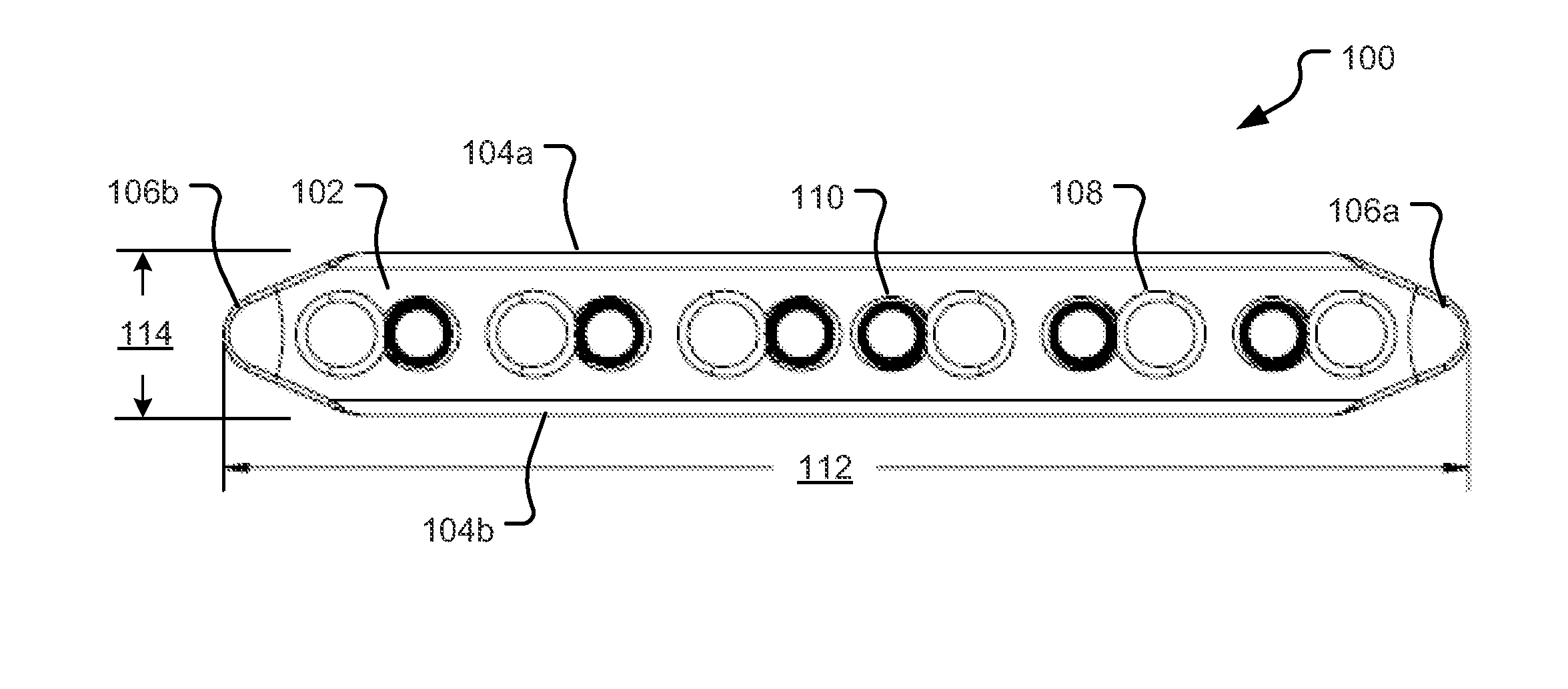
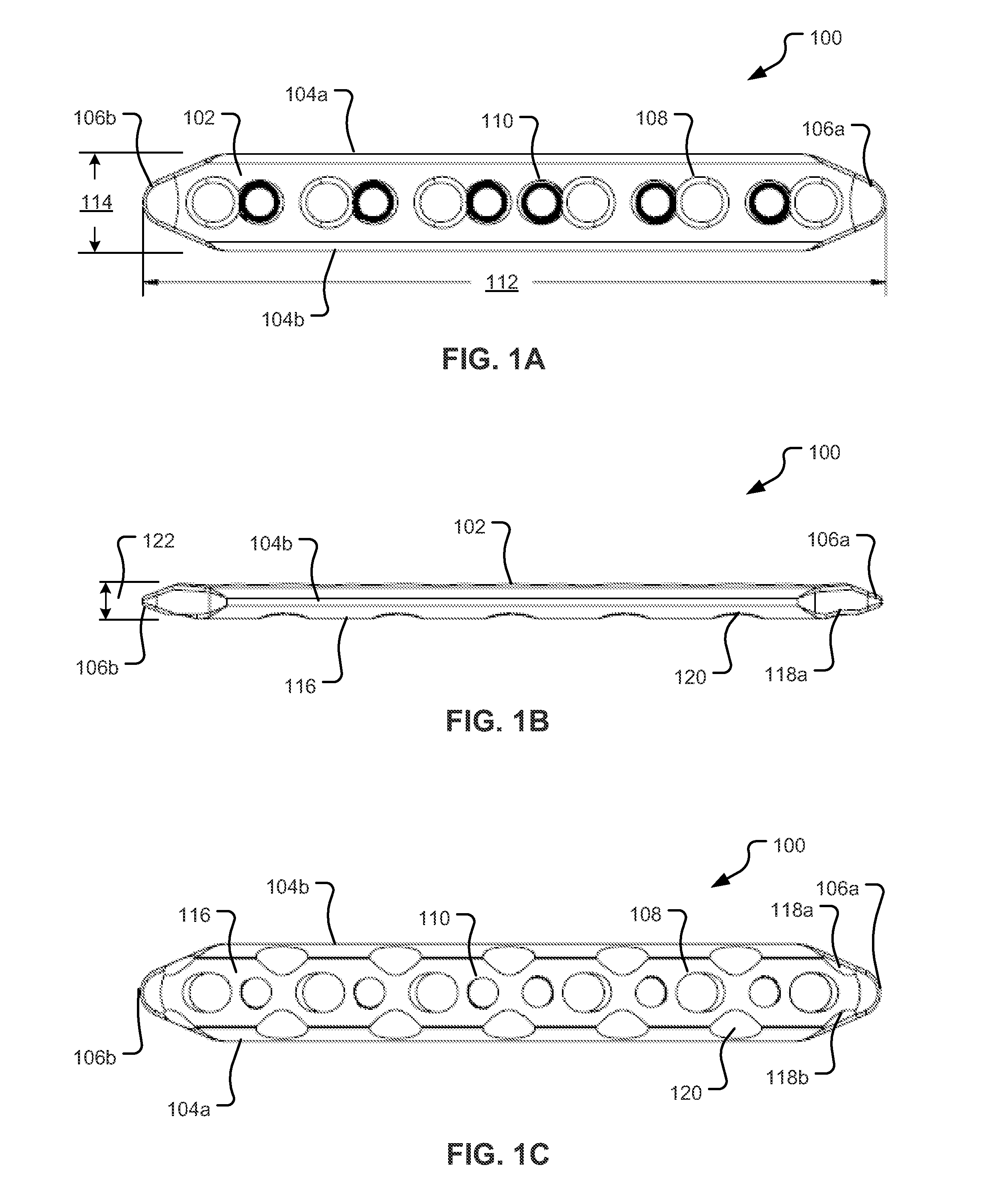
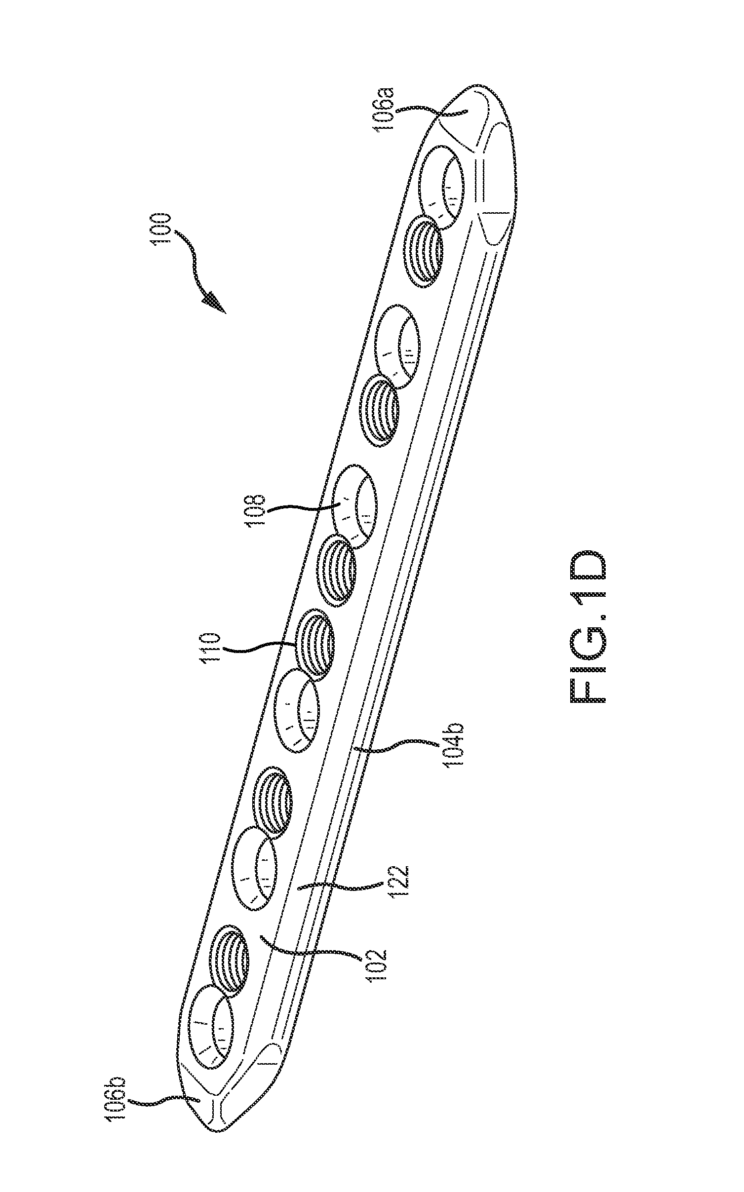
[0026]Bones fracture in any number of various ways and, in order to properly reduce a fracture, it may be necessary to place compression screws in any number of combinations along a bone plate to bring the various bone fragments together. A bone plate is provided with an optimal number and combination of threaded holes and non-threaded holes. In embodiments,...


PUM


Abstract

Bones fracture in any number of various ways and, in order to properly reduce a fracture, it may be necessary to place compression screws in any number of combinations along a bone plate to bring the various bone fragments together. A bone plate is provided with an optimal number and combination of threaded holes and non-threaded holes. In embodiments, the bone plate comprises one or more “hole pairs” in which a non-threaded hole and a threaded hole are placed adjacent to one another. The use of hole pairs enables a surgeon to place a compression screw and a locking screw in close proximity, facilitating both bone reduction and bone plate stabilization in a proximate location on the bone plate. In embodiments, the bone plate has an optimal thickness that promotes structural integrity while maximizing the number and combination of holes and reducing the profile of seated screws.

Description

INTRODUCTION[0001]Bone plates are used to provide structural support for fixation of various types of bone fractures. Bone plates are generally constructed of metal, e.g., titanium, and may be fabricated in a number of different shapes and sizes to conform to different types of bone for use with different types of fractures. In operation, bone plates are secured to the bone to “reduce” the fracture, i.e., bring bone fragments into alignment and close proximity to facilitate the body's natural bone growth and healing. Bone reduction is generally accomplished using compression screws. Compression screws have threaded shafts and are anchored through holes in the bone plate and into the various bone fragments, which upon tightening pull the bone fragments together under a compression load against the plate. However, due to dynamic loading caused by physiological movement, the angular relationship between the bone plate and the compression screws may loosen over time.[0002]Securing or lo...

Claims


Application Information

Patent Timeline
Patent Type & Authority Patents(United States)
IPC IPC(8): A61B17/88A61B17/80A61B17/86
CPCA61B17/8014A61B17/8057A61B17/8085A61B17/8605
Inventor MAROTTA, JOHNTRAFKA, VICTORIA
Owner CARDINAL HEALTH 247 INC
Why Eureka
Try Eureka