Door sensor and door equipped with such door sensor

a door sensor and door technology, applied in the field of door sensors, can solve the problems of difficult installation procedures, complicated constitutions, and inability to use them, and achieve the type of constitutions that cannot be achieved

Active Publication Date: 2004-07-22
OPTEX CO LTD
View PDF3 Cites 98 Cited by
  • Summary
  • Abstract
  • Description
  • Claims
  • Application Information

AI Technical Summary

Benefits of technology

0024] In the case of the former constitution (i.e., a constitution in which door sensor(s) are attached to surface(s) facing toward direction(s) toward which door body or bodies move during opening thereof) it will be possible to prevent the door body or bodies from coming in contact with person(s) or the like when the door body or bodies are being opened; and in the case of the latter constitution (i.e., a constitution in which door sensor(s) are attached to surface(s) facing toward direction(s) toward which door body or bodies move during closing thereof) it will be possible to prevent the door body or bodies from coming in contact with person(s) or the like when the door body or bodies are being closed. Particularly in the latter case it will be possible for activation sensor(s) to also serve as door sensor(s).
0025] In a specific example of the overall constitution of a door sensor, sensor package(s) might be provided, and door position detecting means, object detecting means, and object determining means might be housed within such sensor package(s). This being the case, procedures for attaching the present door sensor(s) to door(s) might be such that sensor package(s) could be attached to door surface(s) by means of adhesive or the like, facilitating attachment procedures.

Problems solved by technology

However, there has not to date been a proposal in connection with the carrying out of such determination as would permit adequate reliability to be attained with a simple constitution.
However, with such a constitution, not only would there be a need to add a new capability, i.e., ability to identify angular displacement position, to the door drive mechanism, but there would also be a separate need for wiring to permit the output signal from the door drive mechanism to be sent to the far-side sensor, which would tend to make the constitution more complex and complicate installation procedures.
Furthermore, because door drive mechanisms of automatic swing doors which have already been installed will perforce not have been provided with ability to identify the angular displacement position, employment of this constitution therein will, practically speaking, be impossible.
That is, such a constitution is not of the type that can be achieved by retrofitting a preexisting automatic swing door.
Furthermore, the aforementioned problematic situation is not limited to automatic swing doors but may also arise in like fashion with automatic revolving doors, automatic folding doors, upward-pivoting gate doors, and the like.
Moreover, with such doors, the aforementioned problematic situation may arise in like fashion when applied to a door sensor functioning as a safety sensor during closing (e.g., in the event that the aforementioned near-side sensor is made to function as a safety sensor, etc.).

Method used


Image

  • Door sensor and door equipped with such door sensor
  • Door sensor and door equipped with such door sensor
  • Door sensor and door equipped with such door sensor

Examples


embodiment 1

[0046] Embodiment 1

[0047] A first embodiment will first be described. The present embodiment concerns a situation in which the present invention has been applied to an automatic swing door.

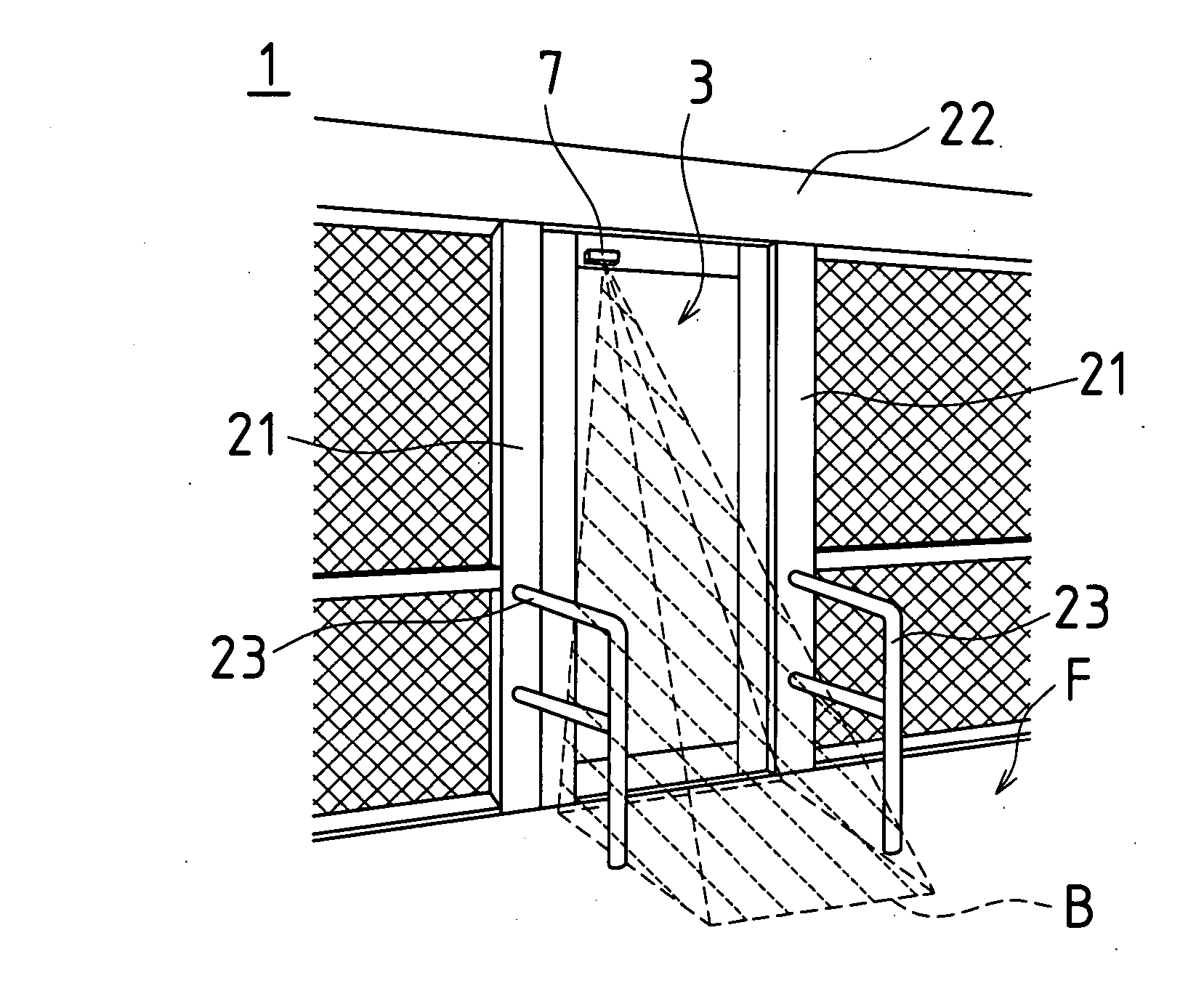
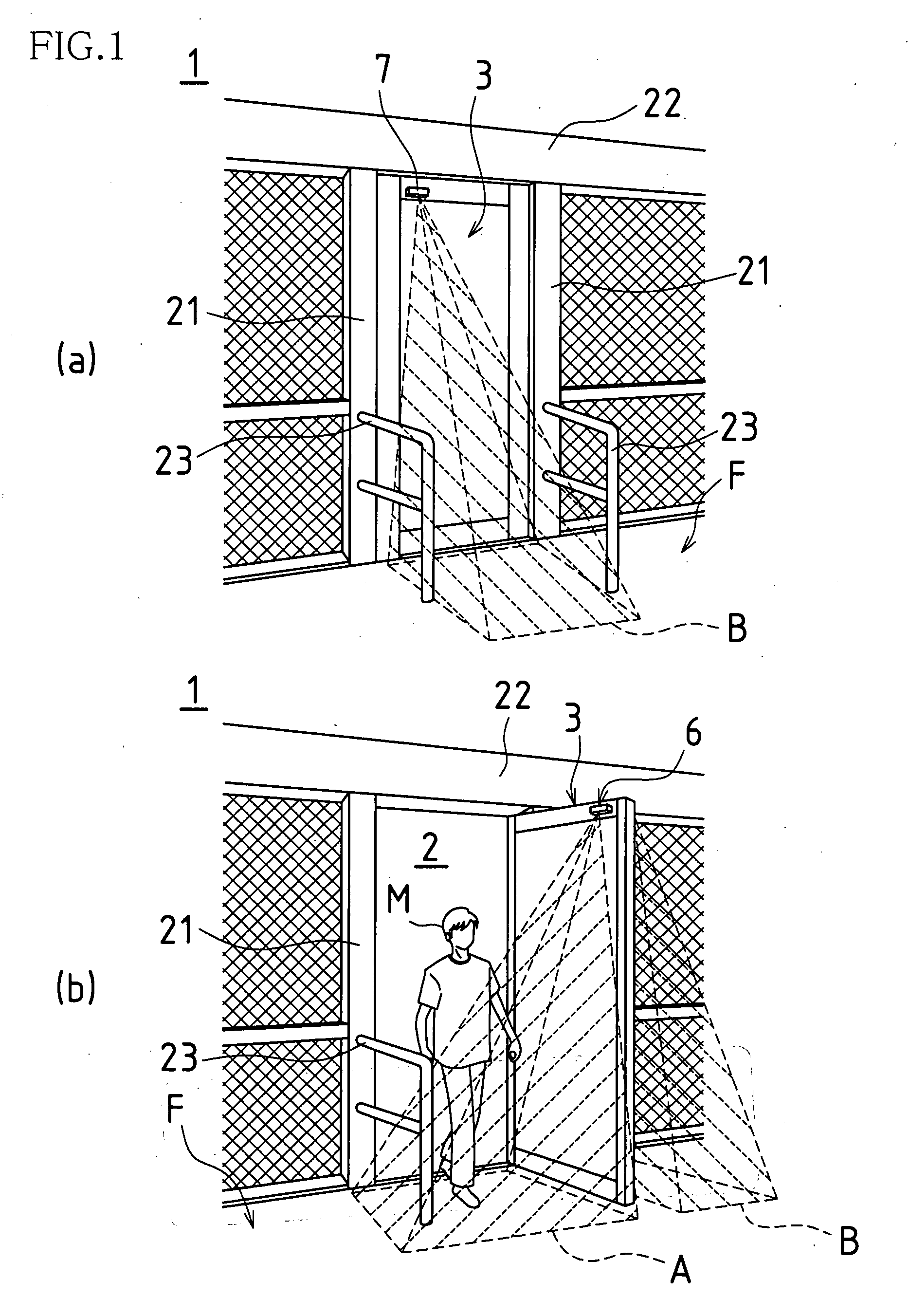
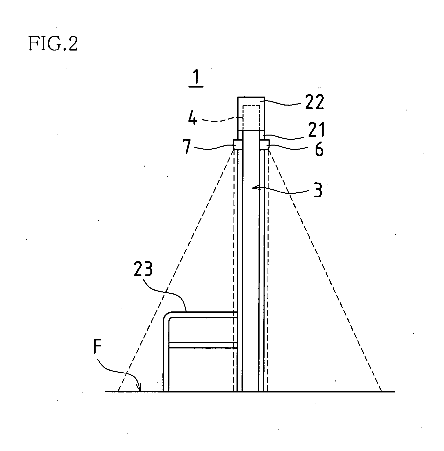
[0048] FIG. 1 contains oblique views of an automatic swing door 1 associated with the present embodiment, (a) showing the door in its closed state and (b) showing the door in its open state. FIG. 2 is a side view of automatic swing door 1 when in its closed state. FIG. 3 is a block diagram showing a control system for this automatic swing door 1.

[0049] --Description of Overall Constitution of Automatic Swing Door 1--

[0050] As shown in FIGS. 1 and 2, at this automatic swing door 1, door opening 2 is formed from pair of side jambs 21, 21, which are arranged perpendicularly and with prescribed distance therebetween over floor F, and header 22, which straddles the top portions of these two side jambs 21, 21. In addition, attached to this door opening 2 is door body 3 of shape and size as will permit c...

embodiment 2

[0079] Embodiment 2

[0080] A second embodiment of the present invention will next be described. The present embodiment concerns a situation in which the present invention has been applied to an automatic revolving door.

[0081] FIG. 6 is a plan view of an automatic revolving door 1 associated with the present embodiment. FIG. 7 is a block diagram showing a control system for this automatic revolving door 1.

[0082] Automatic revolving door 1 of the present embodiment comprises four door bodies 3, 3, . . . spaced 90 degrees apart and joined together so as to rotate as a single unit. Furthermore, at the present automatic revolving door 1, a door sensor 7, more or less identical in constitution to the far-side sensor of the foregoing first embodiment, is attached to each door body 3. More specifically, these are mounted on each door body 3 in the vicinity of a location which is at the top thereof and which is more or less centrally located along the width direction thereof. Here, only the a...


PUM


Abstract

Door sensor(s) 6, 7 may be attached to door body or bodies 3 of automatic swing doors. Door sensor(s) 6, 7 may be equipped with door position detecting means 67, 77 comprising geomagnetic sensor(s); sensor(s) 6, 7 being itself or themselves capable of detecting position(s) occupied by door body or bodies 3 during opening and/or closing thereof. During opening and/or closing of door body or bodies 3, determination may be made as to whether detected object(s) are object(s) intended for detection; and in the event that object(s) are object(s) intended for detection, opening and/or closing of door body or bodies 3 may be stopped, slowed, and/or reversed in correspondence to detected position(s) occupied by door body or bodies 3 during opening and/or closing thereof.

Description

BACKGROUND OF INVENTION[0001] The present invention relates to a door sensor with which a swing door or the like may be equipped and to a door equipped with such a door sensor. In particular, the present invention pertains to a strategy for achieving simplified door sensor constitution.[0002] A typical automatic swing door will conventionally be positioned in a closed position such that the door body closes off the door opening under circumstances where no one is approaching the door. Furthermore, in the event that someone approaches the door from one side, this side representing the near side thereof, the door body can be made to swing toward the side opposite the near side, this opposite side representing the far side thereof, clearing the door opening and allowing passage therethrough.[0003] In order to be able to cause such opening operations to occur, this type of door might be provided with a near-side sensor on the near-side face of the header constituting the upper frame of ...

Claims


Application Information

Patent Timeline
Patent Type & Authority Applications(United States)
IPC IPC(8): E05F15/20G08B13/08H02P1/00
CPCE05Y2400/54E05Y2600/46E05Y2800/40E05F2015/483E05F15/43E05F15/608E05F15/74E05Y2900/132E05F15/611
Inventor OKABE, JUNICHIROMATSUYAMA, TOSHIYASU
Owner OPTEX CO LTD
Why Eureka
Try Eureka