Collapsible canopy and framework therefor

Inactive Publication Date: 2004-07-29
MATTHEWS JOHN T +1
View PDF54 Cites 33 Cited by
  • Summary
  • Abstract
  • Description
  • Claims
  • Application Information

AI Technical Summary

Benefits of technology

0010] It is another object of the present invention to provide a canopy framework incorporating improved fittings that reduce cost while providing sufficient sturdiness and lateral stability during use.
001

Problems solved by technology

A problem experienced by the structures shown in U.S. Pat. No.
'656 (Carter) as well as many other frameworks for canopy structures is that the edge scissor assemblies extending between the adjacent upright support members are often subjected to lateral forces which tend to decrease their stability.
It was often found

Method used


Image

  • Collapsible canopy and framework therefor
  • Collapsible canopy and framework therefor
  • Collapsible canopy and framework therefor

Examples


Embodiment Construction

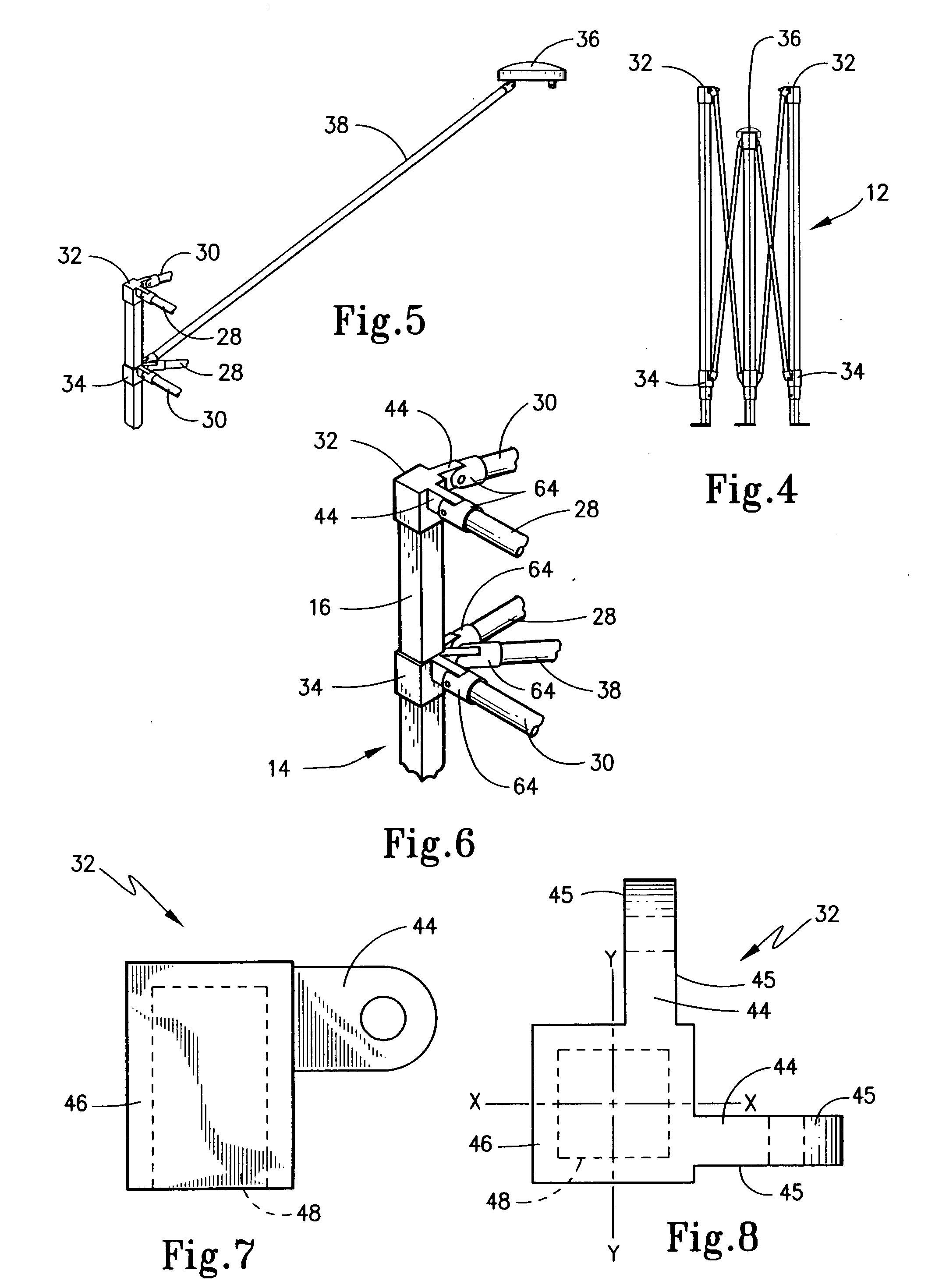
[0057] The present invention is broadly directed to canopy structures that form shelters or shade devices to temporarily protect users against the elements, to provide privacy and the like. In addition, the present invention is directed to framework assemblies that support canopy coverings for such canopies. This invention specifically concerns fittings that interconnect various structural elements of the framework in a collapsible canopy.

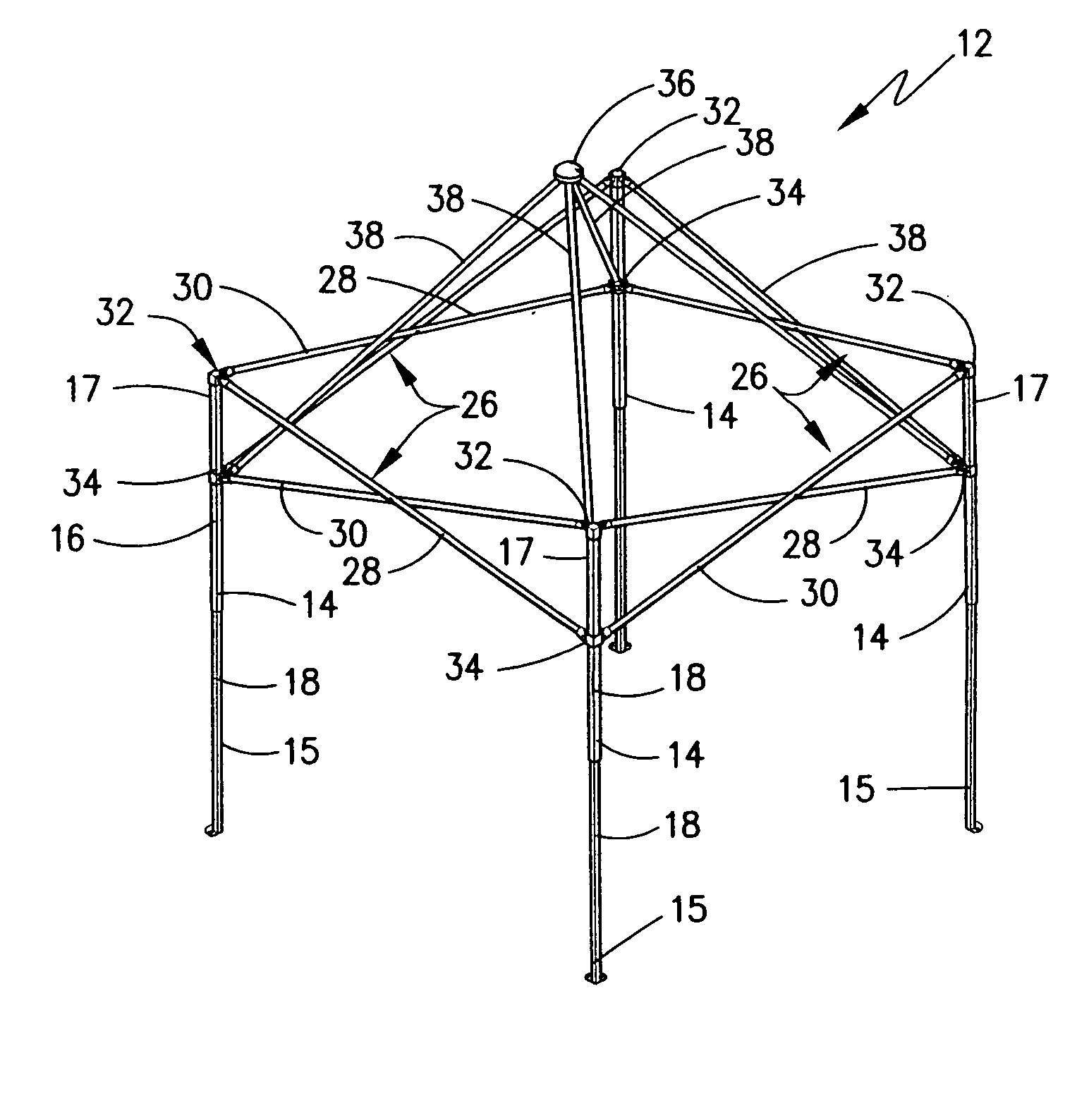
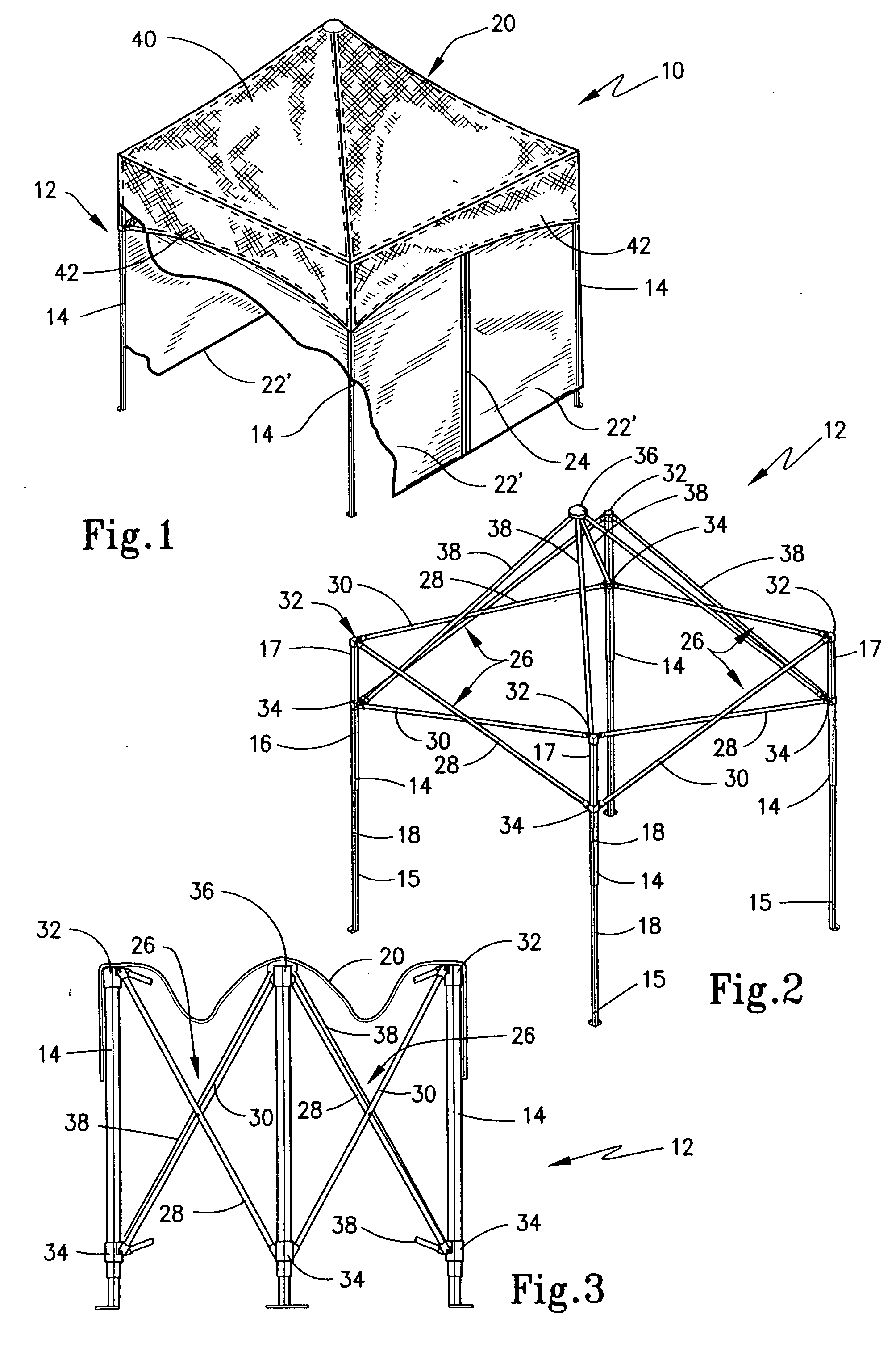
[0058] To introduce this invention, a representative canopy 10 is shown in FIG. 1 as well as a framework 12 for such canopy as is shown in FIG. 2. In each of these figures, canopy 10 and framework 12 are depicted in a fully erected state. As is shown, framework 12 includes a plurality of upright supports 14 that form legs disposed at each corner of canopy 10. Upright supports 14 have bottom end portions 15 positionable on a support surface and opposite top end portions 17. Each of upright supports 14 is formed by a pair of telescoping sections 16 a...


PUM


Abstract

An expandable framework is provided that can move between an expanded state in use and a collapsed state for storage. A canopy covering is supported by the framework to form an expandable canopy. The framework includes a plurality of upright support members with adjacent ones of which being interconnected by edge scissor assemblies. Upper and lower mounts are located on the support members with some of the mounts having a lobe with outwardly facing substantially parallel sidewalls. At least some of the outer ends of the scissor assemblies are provided with socket fittings that have spaced-apart portions that define a channel opening therebetween to receive a lobe in close-fitted engagement wherein at least one of the portions has a substantially flat face that forms a sliding contact surface with the lobe. A fastener secures each lobe in a respective socket for pivotal movement.

Description

[0001] The present invention generally relates to shelters and shade devices which may be used to temporarily shelter against the elements, to provide privacy and the like. More particularly, the present invention relates to a collapsible canopy and the collapsible framework therefor which may be quickly erected for use yet easily collapsed for compact storage. The invention specifically concerns improved fittings that interconnect various structural elements of the framework in this collapsible canopy.[0002] Portable shelters have been in existence since pre-historic times. Over the last 20 years, however, there has been a dramatic increase in the sophistication, quality and construction of portable structure apparatus. Examples of such improvements are found in U.S. Pat. No. 4,607,656 issued Aug. 26, 1986 to Carter as well as U.S. Pat. No. 4,641,676 issued Feb. 10, 1987 to Lynch. Each of these patents discloses a portable canopy structure that has a framework that may be collapsed...

Claims


Application Information

Patent Timeline
IPC IPC(8): E04H15/50
CPCE04H15/50
Inventor MATTHEWS, JOHN T.MARTIN, TIMOTHY J.
Owner MATTHEWS JOHN T
Why Eureka
Try Eureka