USB-chargeable emergency light structure

a technology of emergency light and charging device, which is applied in the direction of fixed installation, coupling device connection, lighting and heating apparatus, etc., can solve the problems of incompatibility of conventional emergency light and electric appliances, limited use of conventional emergency light, and inability to provide other functions of electric recharging devices

Inactive Publication Date: 2004-07-29
LIAO SHENG HSIN
View PDF3 Cites 66 Cited by
  • Summary
  • Abstract
  • Description
  • Claims
  • Application Information

AI Technical Summary

Problems solved by technology

A conventional emergency light is limited to insertion in an electric socket only for domestic power distribution.
However, the conventional emergency light is not compatible with these electric appliances.
Furthermore, a conventional charging device cannot provide functions other than electric recharging.

Method used


Image

  • USB-chargeable emergency light structure
  • USB-chargeable emergency light structure
  • USB-chargeable emergency light structure

Examples


Embodiment Construction

[0019] Wherever possible in the following description, like reference numerals will refer to like elements and parts unless otherwise illustrated.

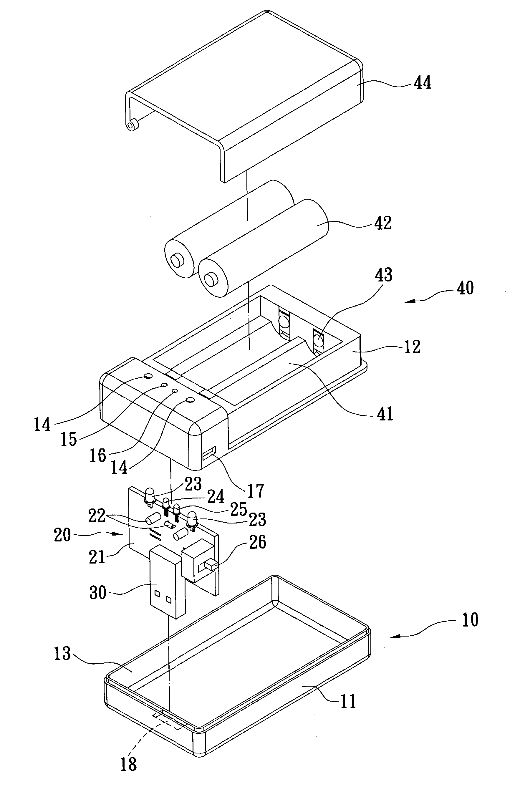
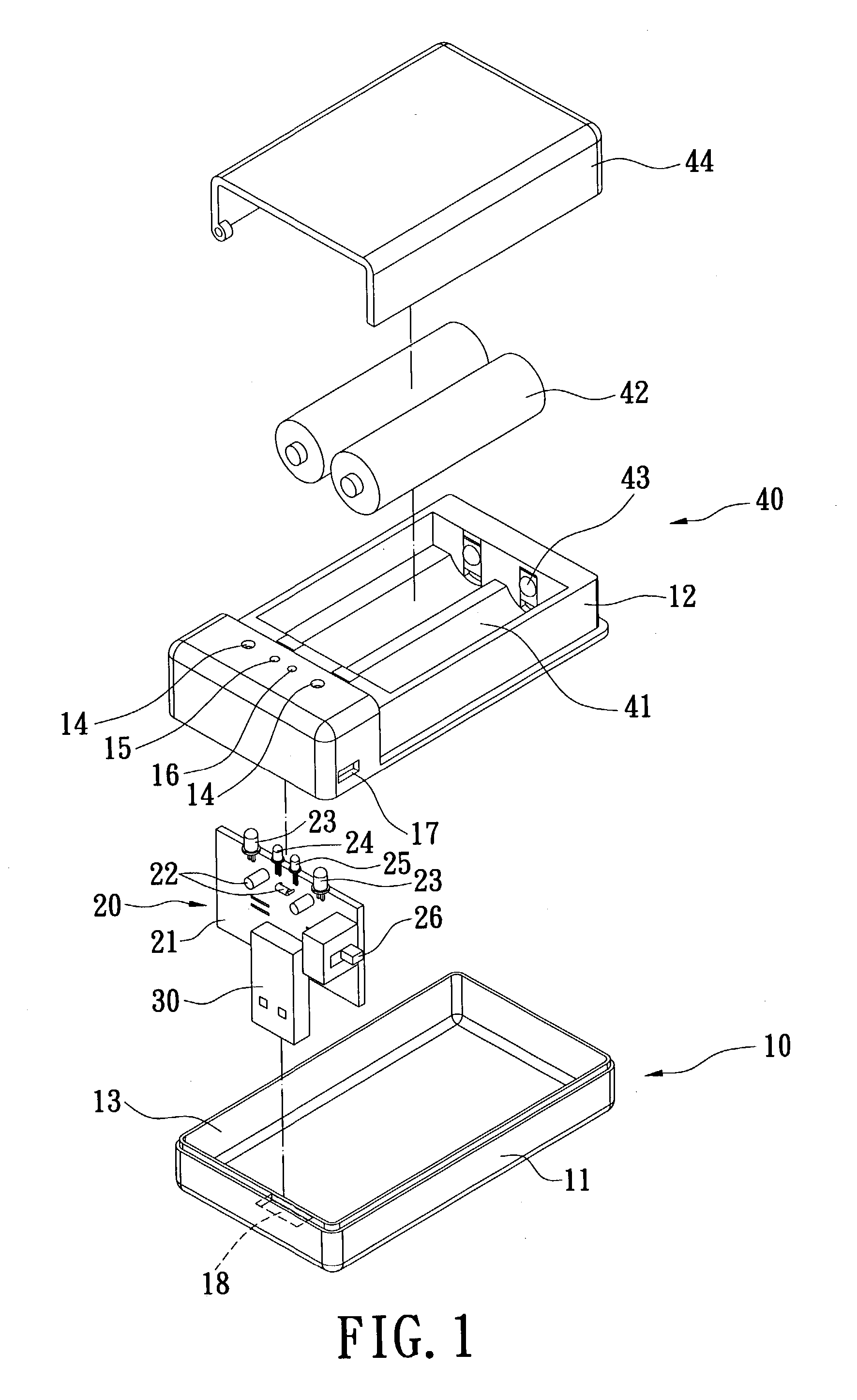
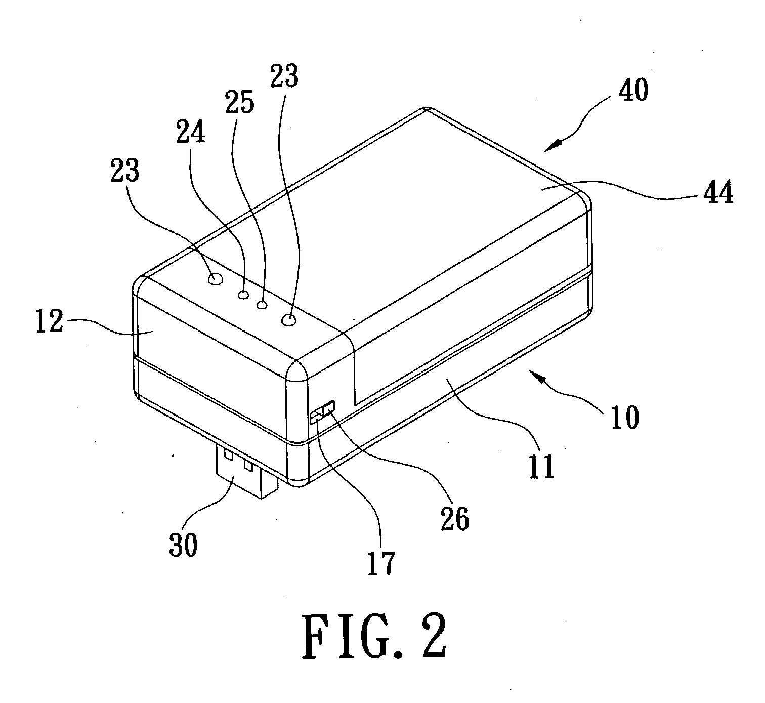
[0020] Referring to FIGS. 1-3, the invention provides a multi-functional USB-chargeable emergency light structure that includes a light base 10, a charging / outputting circuit unit 20, a connector 30 and a charging socket 40. The light base 10 includes a first base portion 11 and a second base portion 12 that are connected to each other by a snap fitting, clasps, screws, or ultrasonic welding to define an accommodating space 13 for receiving the charging / outputting circuit unit 20. A plurality of light holes 14, 15, 16, a switch hole 17 and a connector hole 18 are respectively formed through an external surface of the light base 10.

[0021] The charging / outputting circuit unit 20 includes a circuit board 21 and a plurality of electronic components 22. The charging / outputting circuit unit 20 receives an electric power input and performs chargi...


PUM


Abstract

A USB-chargeable emergency light structure has a light base, a charging/outputting circuit unit, a connector and a charging socket. The light base defines an accommodating space therein for receiving the charging/outputting circuit unit that has a plurality of light sources. The connector partially protrudes from the base and is electrically connected to the charging/outputting circuit unit. The connector is a USB connector. The charging socket is mounted on the light base and electrically connected to the charging/outputting circuit unit. The lighting structure thereby constructed can be used as an emergency light, a night light, a flashlight or a charging device.

Description

[0001] 1. Field of the Invention[0002] The invention relates to a USB-chargeable emergency light structure and, more particularly, to a USB-chargeable emergency light structure which can be used as an emergency light, a night light, a flashlight or a charging device.[0003] 2. Description of the Related Art[0004] An emergency light typically emits light when there is a failure of electric power supply. A conventional emergency light is limited to insertion in an electric socket only for domestic power distribution.[0005] As the electronic industry progresses, electric appliances such as a desktop computer, a laptop computer, a cellular phone or a personal digital assistant (PDA) have become increasingly common everywhere. However, the conventional emergency light is not compatible with these electric appliances. Furthermore, a conventional charging device cannot provide functions other than electric recharging.SUMMARY OF INVENTION[0006] It is therefore one object of the invention to ...

Claims


Application Information

Patent Timeline
Patent Type & Authority Applications(United States)
IPC IPC(8): F21L4/08F21S8/00F21V23/06F21V27/00F21V33/00H01R13/66H01R13/713H01R13/717H01R13/72H01R31/06H01R35/04
CPCF21L4/08F21S8/035F21V23/06F21V27/005F21V33/0052H01R13/6658H01R35/04H01R13/717H01R13/7172H01R13/7175H01R13/7177H01R13/72H01R31/065H01R13/713
Inventor LIAO, SHENG HSIN
Owner LIAO SHENG HSIN
Why Eureka
Try Eureka