Head-mounted display

a display and head technology, applied in the field of head-mounted displays, can solve the problems of increasing eye fatigue, too large size for convenient storage in a helmet, and the inability of conventional hmds to reduce the size of the display,

Inactive Publication Date: 2004-08-05
SAMSUNG ELECTRONICS CO LTD
View PDF12 Cites 22 Cited by
  • Summary
  • Abstract
  • Description
  • Claims
  • Application Information

AI Technical Summary

Problems solved by technology

While a magnifier-type HMD can produce a virtual image with a large field of view through a very small magnifier lens, it increases eye fatigue.
AN HMD using a relay lens reduces eye fatigue because a viewer can observe an image displayed on the screen from a distant position, but its size is too large to be conveniently contained in a helmet.
However, as described above, the conventional HMD cannot reduce its size because it requires a plurality of optical components such as condensing lens 2, reflectors 3 and 4, and eyepiece 5 between the point light source 1 and image plate 6.
Furthermore, it cannot provide a sufficiently high resolution since an incandescent lamp is used as the point light source 1.

Method used


Image

  • Head-mounted display
  • Head-mounted display
  • Head-mounted display

Examples


Embodiment Construction

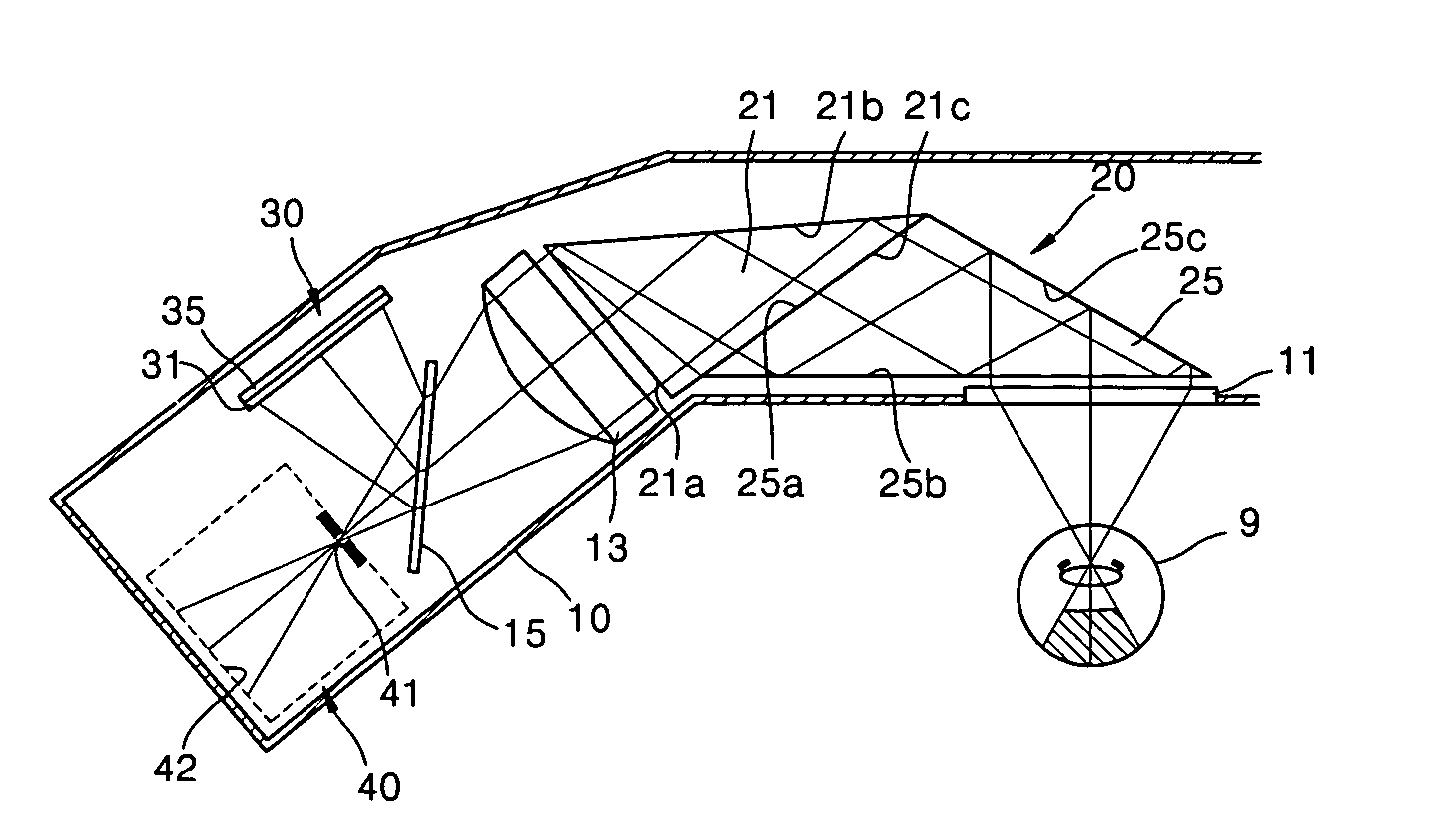
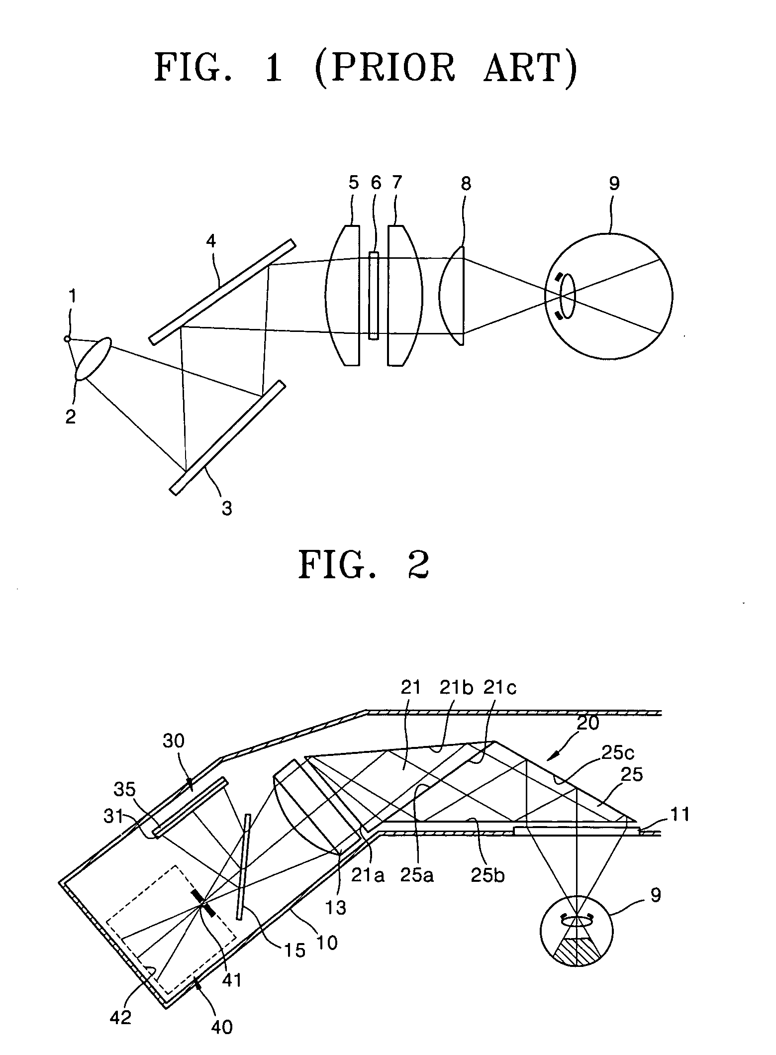
[0019] Head-mounted displays (HMDs) according to illustrative, non-limiting embodiments of the present invention will now be described in detail with reference to the accompanying drawings.

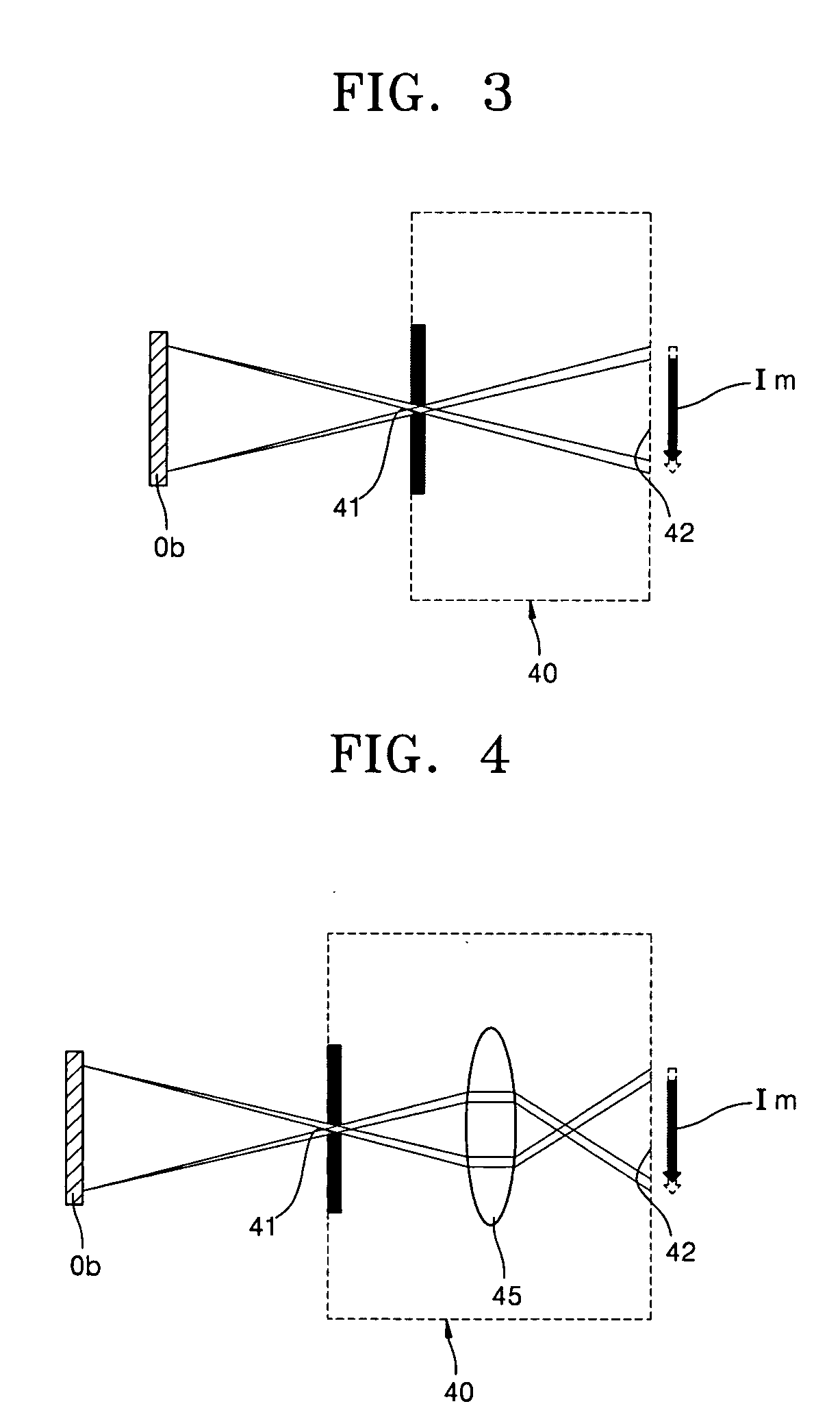
[0020] Referring to FIG. 2, an HMD includes an image-forming unit 30 that produces and emits an image, a half mirror 15 that reflects a part of image received from the image-forming unit 30 and transmits the remaining part, a pinhole 41, a collimating lens 13 disposed opposite the half mirror 15, a prism unit 20 disposed opposite the collimating lens 13 from the half mirror 15 and for guiding the path of an incident image, and a Fresnel lens 11 that focuses the incident image onto an eyeball 9.

[0021] The Fresnel lens 11 with a diffraction pattern on a flat plate is constructed to focus an incident image through the diffraction pattern. The Fresnel lens 11 preferably, but not necessarily, has a Fresnel pattern corresponding to the aspheric shape to correct chromatic aberration. Here, the aspheric s...


PUM

PropertyMeasurementUnit
diameteraaaaaaaaaa
shapeaaaaaaaaaa
chromatic aberrationaaaaaaaaaa

Abstract

A head-mounted display (HMD) is provided. The HMD includes: an image-forming unit that produces and emits an image; a half mirror disposed obliquely with respect to the image-forming unit for transmitting some part of the image entering from the image-forming unit and transmitting the remaining part; a pinhole located at a focal point of the image reflected from the half mirror for transmitting the incident image and focusing the transmitted image onto a dark space within the housing; a collimating lens disposed opposite the pinhole with respect to the half mirror for converging the incident divergent image and producing parallel light; a prism unit disposed opposite the collimating lens for guiding the path of the incident image; and a Fresnel lens disposed opposite a part of the prism unit for focusing the incident image onto an eyeball. A user wearing the HMD can view the image formed in the housing through the pinhole.

Description

[0001] This application claims priority from Korean Patent Application No. 2002-76995, filed Dec. 5, 2002, the contents of which are incorporated herein by reference in their entirety.[0002] 1. Field of the Invention[0003] The present invention relates to a head-mounted display (HMD) designed to view video images when mounted on a user's head and, more particularly, to a head-mounted display using retinal direct projection and having a small size and high resolution.[0004] 2. Description of the Related Art[0005] In general, head-mounted displays (HMDs) appear in the form of eyeglasses or helmets. AN HMD is a personal see-through device designed to display video images to a user. The HMD is considered a magnifier-type HMD, an optical relay lens-type HMD, or a retinal direct projection-type HMD depending on the optical system configuration.[0006] While a magnifier-type HMD can produce a virtual image with a large field of view through a very small magnifier lens, it increases eye fati...

Claims


Application Information

Patent Timeline
Patent Type & Authority Applications(United States)
IPC IPC(8): G02B27/02G02B27/00G02B27/01
CPCG02B27/0172G02B2027/0178G02B2027/0132G02B27/02
Inventor TOMONO, TAKAO
Owner SAMSUNG ELECTRONICS CO LTD
Why Eureka
Try Eureka