Medical image processing system and method for processing medical image

a medical image and processing system technology, applied in image enhancement, instruments, applications, etc., can solve the problems of large heat exhaustion, large space occupied by monitors, high cost of high-performance monitors, etc., and achieve the effect of reducing the cost of medical image installation

Inactive Publication Date: 2004-08-05
KONICA MINOLTA MEDICAL & GRAPHICS INC
View PDF9 Cites 122 Cited by
  • Summary
  • Abstract
  • Description
  • Claims
  • Application Information

AI Technical Summary

Problems solved by technology

However, when a medical image is to be displayed on a monitor, the monitor is required to have high performance for providing an image suitable for image diagnosis, and such a high performance monitor is expensive and requires space for installation.
Moreover, such a monitor consumes large amount of electric power, and exhausts large amount of heat.
Consequently, it has been practically difficult to install a monitor for displaying a medical image in all the image diagnosis rooms of the department of radiology and respective clinics except for some hospitals such as a large-scaled hospital or the like.
Furthermore, since a flow of the operation in the hospital from radiography to image diagnosis would largely change, large problems such as change of the workflow, adjustment of human resources and the like occur.
On the other hand, the method for image-diagnosing a medical image outputted on a hardcopy of silver halide film or the like has the following problems, though many hospitals conventionally have practiced the method.
Consequently, there are problems in the method such as film cost, hour for the operation and labor cost.
However, the method has the problem that part of image information is not maintained and therefore it causes trouble in image diagnosis thereof.
However, when a medical image recorded on a recording medium such as film is to be observed, searching for a related image or arranging the related image on Schaukasten takes a lot of trouble.
Moreover, when the related image is arranged along with a medical image to be image-diagnosed, there is the problem that it is hard for a doctor who image-diagnoses the image because the doctor is dazzled by strong light from Schaukasten through a gap between the pieces of film when the doctor moves his / her view.

Method used


Image

  • Medical image processing system and method for processing medical image
  • Medical image processing system and method for processing medical image
  • Medical image processing system and method for processing medical image

Examples


first embodiment

[0157] [First Embodiment]

[0158] In the following, with reference to figures, a first embodiment of the present invention will be described in detail.

[0159] First, its structure will be described.

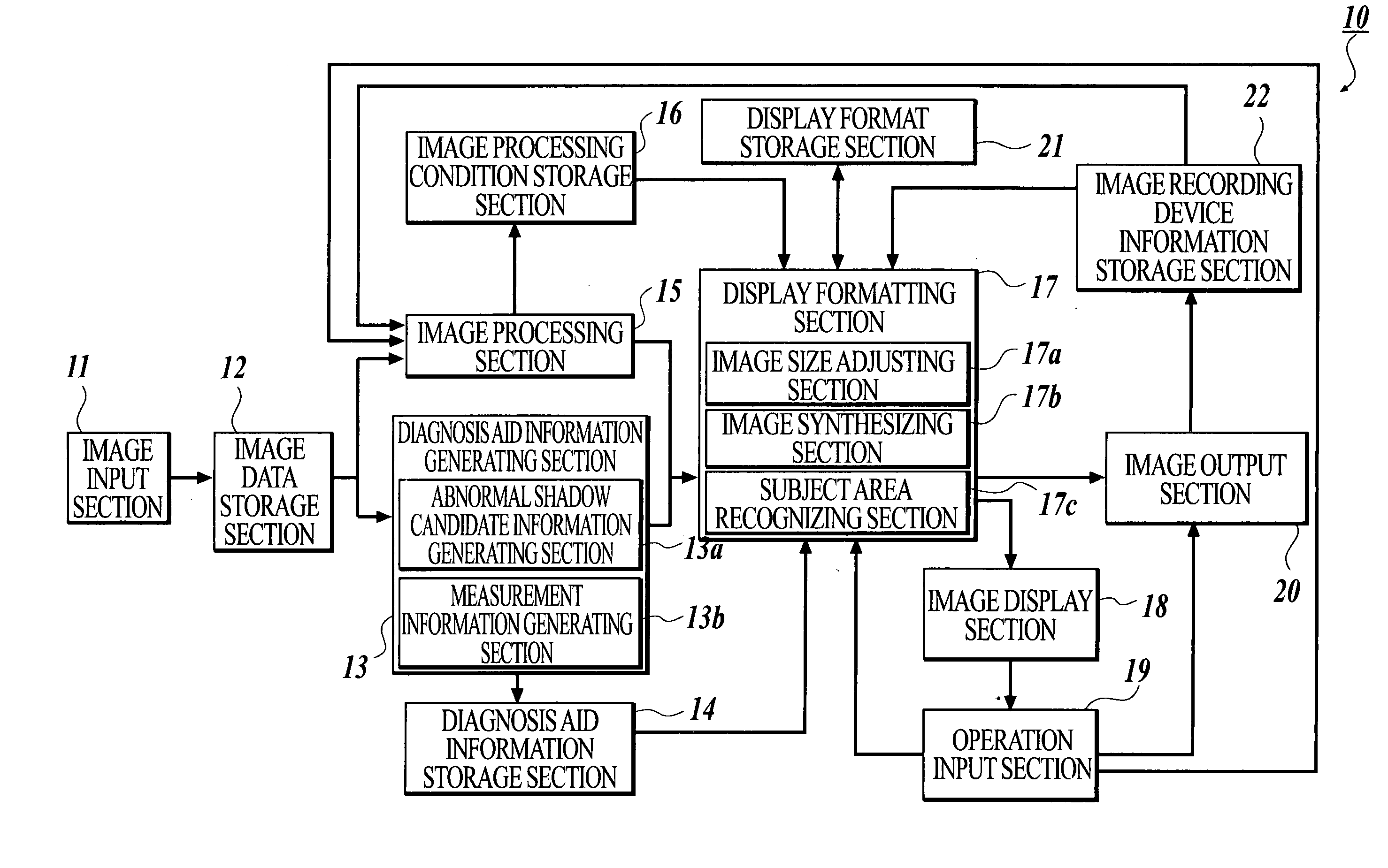
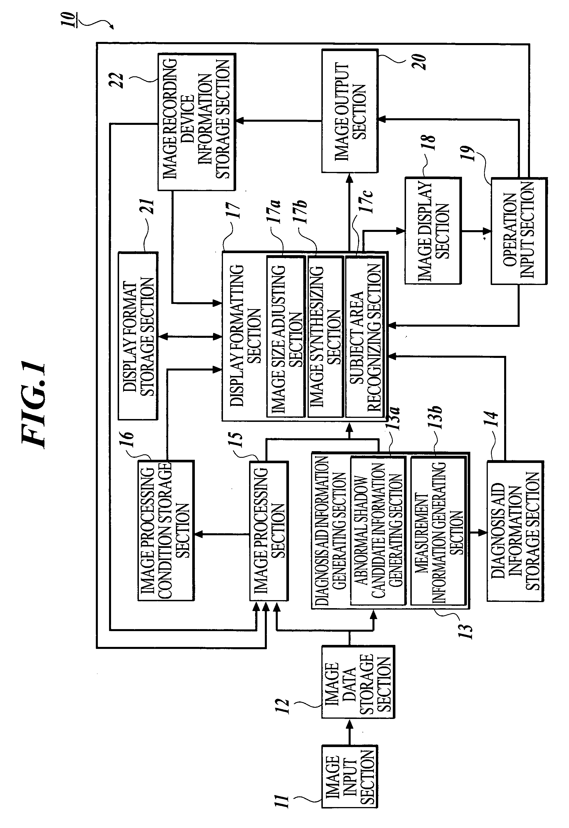
[0160] FIG. 1 is a view showing an inner structure of a medical image processing system 10 in the present embodiment. In FIG. 1, the medical image processing system 10 comprises an image input section 11, an image data storage section 12, a diagnosis aid information generating section 13, a diagnosis aid information storage section 14, an image processing section 15, an image processing condition storage section 16, a display formatting section 17, an image display section 18, an operation input section 19, an image output section 20, a display format storage section 21 and an image recording device information storage section 22.

[0161] The image input section 11 is to scan film on which a medical image obtained by radiographing a patient is recorded with laser beam, to measure amount of tra...

second embodiment

[0246] [Second Embodiment]

[0247] Next, a second embodiment of the present invention will be described.

[0248] As shown in FIG. 11, in the second embodiment, the medical image processing system 10 has a structure having a schema image generating section 23 and a schema image storage section 23 in addition to the structure of the first embodiment.

[0249] The schema image generating section 23 performs contour extraction by analyzing image data inputted from the image data storage section 12 to generate a schema. As an extraction method of contours, as shown in, for example, Japanese Patent Application Publication (Unexamined) No. Tokukai-Sho 63-240832, focusing on a row or a column in image data, in its one-dimensional density data sequence, a specific pattern in which relation of values of data located before and after is in advance determined (for example, a point of local minimum, a point where an inclination is maximum, a point where an inclination is minimum, or the like) is set as...

third embodiment

[0261] [Third Embodiment]

[0262] First, a structure of a third embodiment will be described.

[0263] FIG. 13 is a conceptual diagram showing a whole structure of a medical image processing system 100 in the present embodiment. As shown in FIG. 13, in the medical image processing system 100, image generating devices 3a to 3e, an image processing device 4, an image recording device 5 and the like are connected to one another through a network N in the state capable of data transmitting and receiving thereamong.

[0264] Incidentally, in the present embodiment, an example of the structure in which the image generating devices 3a to 3e, the image processing device 4 and the image recording device 5 are connected to one another through the network N will be described. However, the structure of the system is not limited to such one, and the system structure in which each device is directly connected to one another with wires may be used. Moreover, the number of respective devices and the instal...


PUM


Abstract

A medical image processing system has an image processing section for performing image processing including at least gradation processing on a medical image, a display formatting section for transforming the medical image processed in order to generate an image to be displayed, and an image output section for outputting the image to be displayed to an image recording device, wherein the image processing section generates, based on at least one medical image obtained by radiographing a subject, a plurality of processed images composed of at least one main image and at least one sub image generated by reducing the whole of the at least one medical image, and the display formatting section generates one image to be displayed by synthesizing the main image and the sub image.

Description

[0001] 1. Field of the Invention[0002] The present invention relates to a medical image processing system and a method for processing a medical image that transform a medical image and output the processed image so as to improve efficiency on doctor's image diagnosis.[0003] 2. Related Art[0004] Conventionally, analog images on intensifying screen, film or the like used for radiography, or images obtained from a digital image input system using photostimulable phosphor and outputted as a hardcopy such as silver halide film are used as the medical images to be used by a doctor for diagnosis. Generally, a doctor image-diagnoses such medical images with an image observation device such as Schaukasten or the like in respective clinics.[0005] On the other hand, recently, a system for aiding doctor's diagnosis by means of an image diagnosis aid device has been proposed (see, for example, Japanese Patent Application Publication (Unexamined) No. 2000-287957). Such an image diagnosis aid devi...

Claims


Application Information

Patent Timeline
Patent Type & Authority Applications(United States)
IPC IPC(8): A61B5/107A61B6/00G06K9/00G06T7/00G16H30/40
CPCA61B5/1075A61B6/502A61B5/7232G06T7/0012G06T2207/30068G06F19/321G16H30/40
Inventor YANAGITA, AKIKOYAMANAKA, KENJI
Owner KONICA MINOLTA MEDICAL & GRAPHICS INC
Why Eureka
Try Eureka