
Incandescent lamp for vehicle headlights

a headlight and incandescent technology, applied in the direction of narrow/point lamps, fixed installations, lighting and heating apparatus, etc., can solve the problems of increased parasitic light components and undesirable manners, and achieve the effect of reducing the dimensions of the shading apparatus, improving the suspension of incandescent filaments, and reducing the dimensions of shading apparatus

Inactive Publication Date: 2004-08-19
OSRAM GMBH
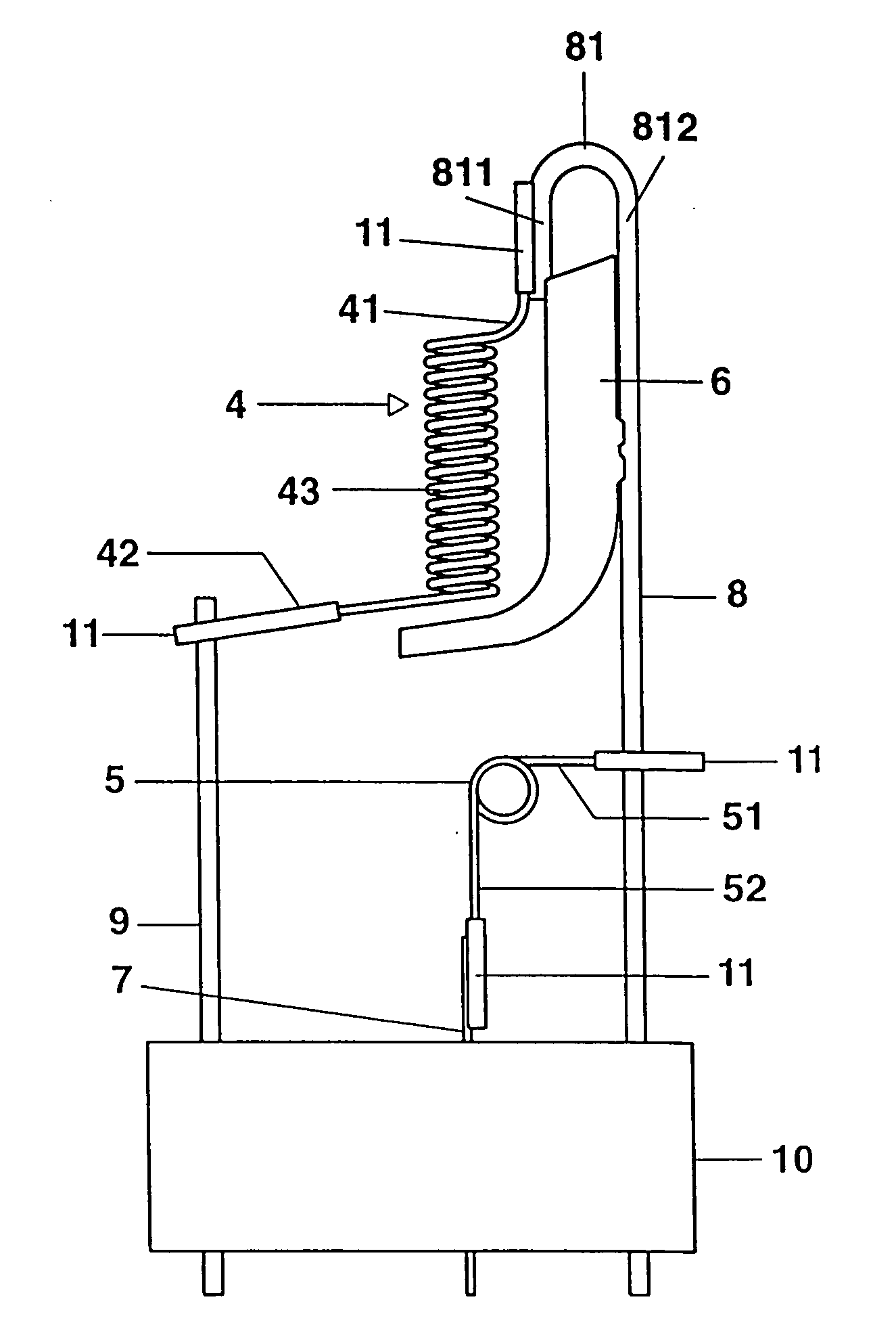
View PDF9 Cites 2 Cited by
  • Summary
  • Abstract
  • Description
  • Claims
  • Application Information

AI Technical Summary

Benefits of technology

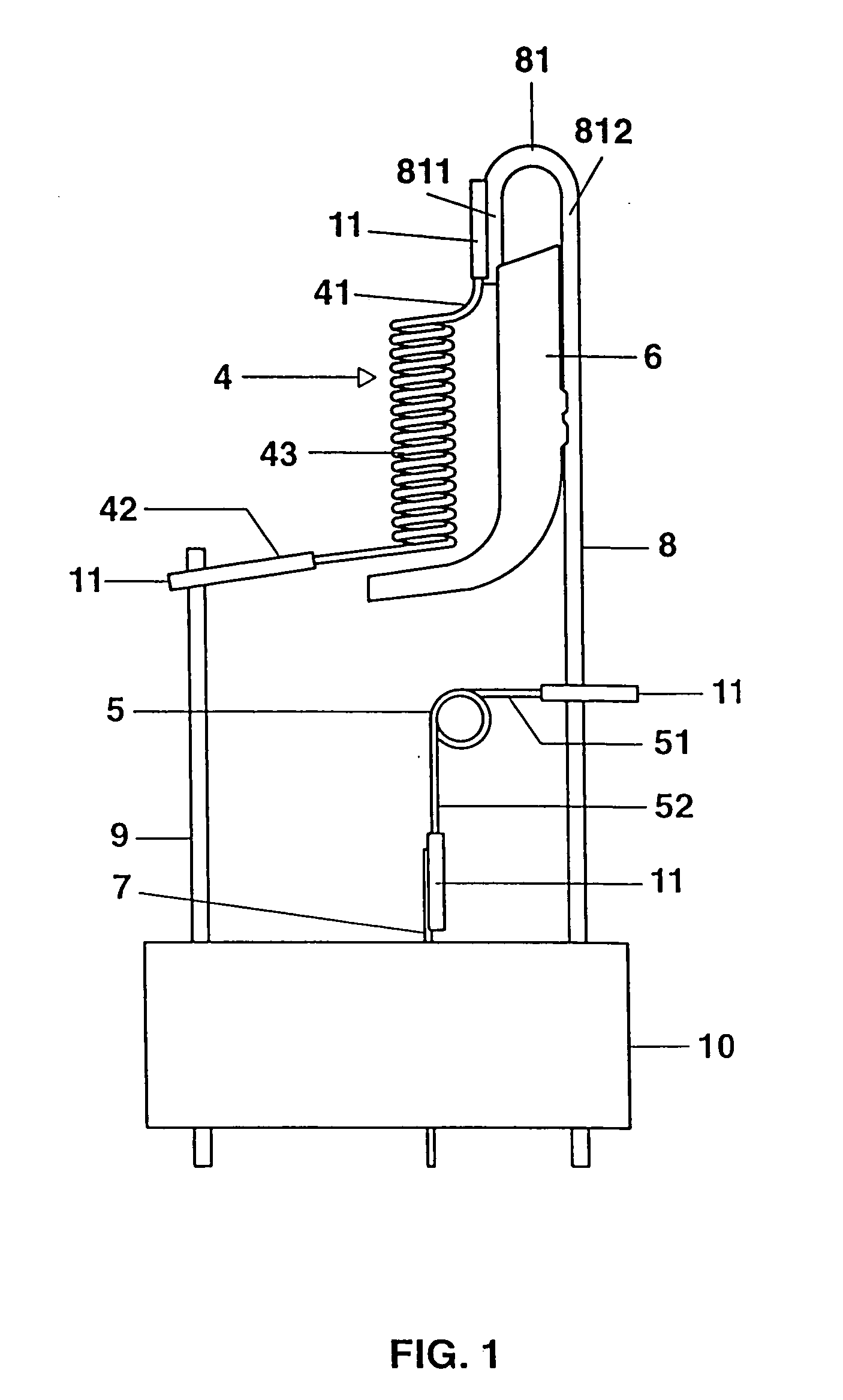
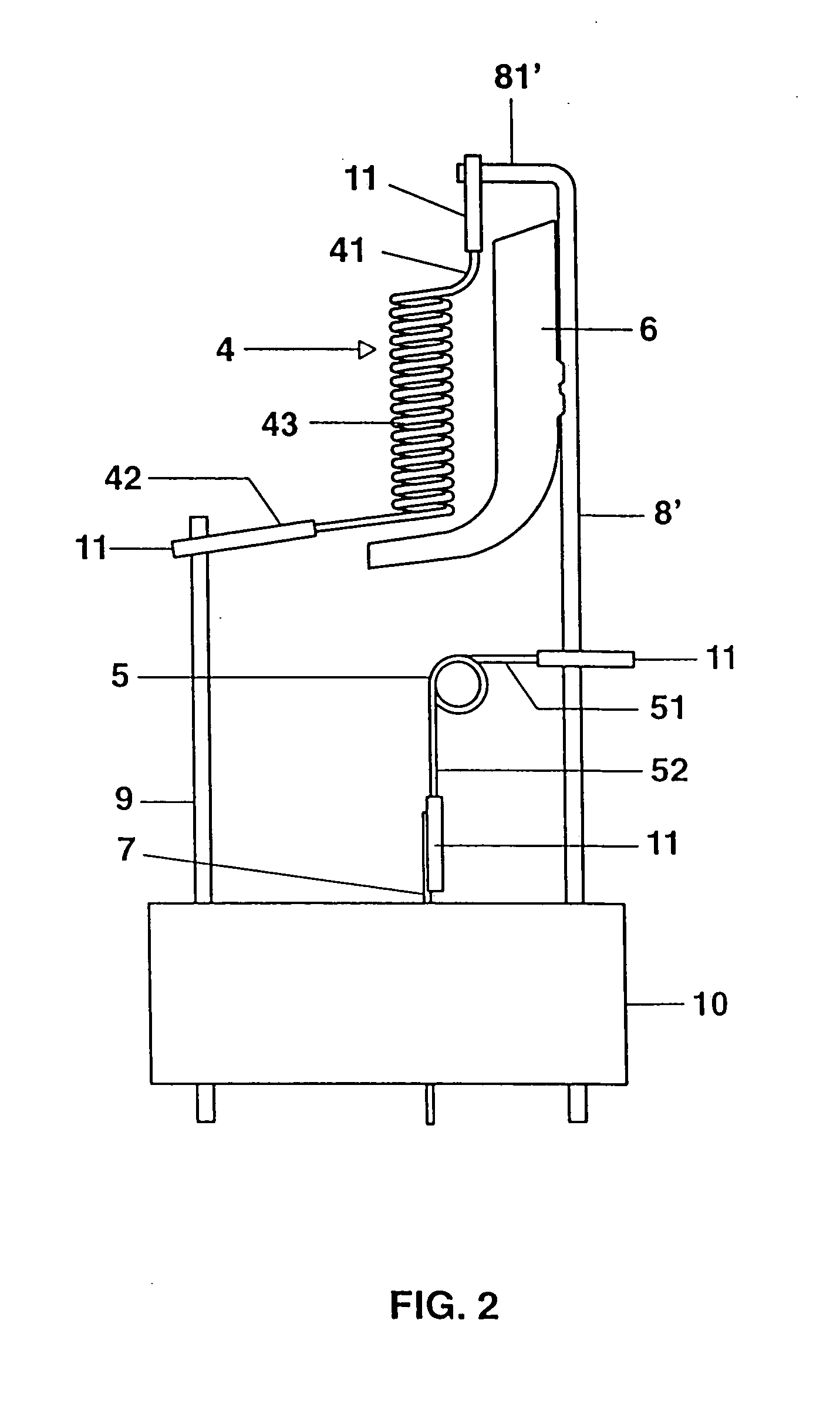
[0005] The incandescent lamp according to the invention has at least one incandescent filament and a shading apparatus for the at least one incandescent filament, which are arranged in a lamp vessel, and power supply lines for the at least one incandescent filament, a first power supply line being connected to the shading apparatus, and the first power supply line having a bent-back end, which is connected to an outgoing filament line of the at least one incandescent filament. These measures improve the suspension of the incandescent filament, since the outgoing filament lines of the incandescent filament are not connected to the shading apparatus but rather connected directly to the power supply wires, and an aperture is not required in the shading apparatus in order to connect the outgoing filament lines of the incandescent filament to the power supply wires. In particular, there is also no need to provide a welded joint on the shading apparatus for an outgoing filament line. This makes it possible to reduce the dimensions of the shading apparatus.
[0006] In order to ensure that the suspension of the filament is as stable as possible, the bent-back end of the first power supply line is advantageously in the form of a hook. The shading apparatus preferably extends between the limbs of the end, in the form of a hook, of the first power supply line. This makes it possible to use the first power supply line both for fixing the shading apparatus and for suspending the filament. There is preferably a welded connection between one limb of the end, in the form of a hook, of the first power supply line and one outgoing filament line of the incandescent filament. The abovementioned limb is advantageously bent back in the direction of the incandescent filament in order to allow for a short outgoing filament line. In addition, the bent-back end or the abovementioned limb of the first power supply line is at a shorter distance from the surface of the shading apparatus which faces the at least one incandescent filament than the section of the at least one incandescent filament which is responsible for the light emission, in order to prevent the light / dark boundary from being impaired by the light which is scattered at the end in the form of a hook. A molybdenum or tantalum metal film advantageously covers the outgoing filament line of the at least one incandescent filament, which is connected to the abovementioned bent-back end of the power supply line, in order to ensure a good welded connection. The molybdenum or tantalum metal film can be welded more effectively to the molybdenum power supply wire than the tungsten outgoing filament line of the incandescent filament.VI.

Problems solved by technology

The aperture may result in the parasitic light component being increased in an undesirable manner.

Method used


Image

  • Incandescent lamp for vehicle headlights
  • Incandescent lamp for vehicle headlights
  • Incandescent lamp for vehicle headlights

Examples


Embodiment Construction

[0011] The preferred exemplary embodiments of the invention are two-filament halogen incandescent lamps which are provided for use in motor vehicle headlights. These lamps have two incandescent filaments 4, 5 and a shading device 6, which are enclosed in an essentially cylindrical, hard-glass or silica-glass lamp vessel 1. The first incandescent filament 4, which is also referred to as the secondary filament, serves the purpose of producing the low beam and is arranged close to the shading device 6, which partially shades the light emitted by the secondary filament 4. The second incandescent filament 5, which is also referred to as the main filament, serves the purpose of producing the high beam. The lamp vessel 1 has a sealed-off end 1a, which is fixed in the lamp base 2. The lamp base 2 has three contact lugs 3, which are each electrically conductively connected to the incandescent filaments 4, 5 via a power supply line 7, 8, 9. The power supply lines 7, 8, 9 are embedded in the s...


PUM


Abstract

The invention relates to an incandescent lamp for vehicle headlights, the incandescent lamp having at least one incandescent filament and a shading apparatus for the at least one incandescent filament, which are both arranged in a lamp vessel, and having power supply lines for the at least one incandescent filament, a first power supply line being connected to the shading apparatus. The abovementioned power supply line has a bent-back end, which is connected to an outgoing filament line of the at least one incandescent filament.

Description

I. TECHNICAL FIELD[0001] The invention relates to an incandescent lamp for vehicle headlights having at least one incandescent filament and a shading apparatus for the at least one incandescent filament, which are arranged in a lamp vessel, and having power supply lines for the at least one incandescent filament, a first power supply line being connected to the shading apparatus. In particular, the invention relates to a two-filament halogen incandescent lamp for motor vehicle headlights.II. BACKGROUND ART[0002] An incandescent lamp of this type is disclosed, for example, in the patent application DE 195 44 012. This patent application describes a two-filament halogen incandescent lamp for a motor vehicle headlight having two incandescent filaments and a shading apparatus, which are arranged in the lamp vessel. One of the incandescent filaments, which is referred to as the secondary filament, generally serves the purpose of producing the low beam, whereas the other incandescent fila...

Claims


Application Information

Patent Timeline
IPC IPC(8): F21V14/02F21S8/10F21W101/10F21Y101/00H01K1/14H01K1/16H01K1/18H01K1/26H01K1/50H01K7/02H01K9/08
CPCH01K1/16H01K9/08H01K1/26H01K1/14
Inventor SEICHTER, CHRISTIANWITTMANN, KLAUS
Owner OSRAM GMBH
Learn More