Punch with punch elements in adjustable positions

a technology of adjustable positions and punch elements, applied in the field of punch elements with adjustable positions, can solve problems such as contamination or even damage of paper, and achieve the effect of easy adjustmen

Inactive Publication Date: 2004-08-26
CHAU LIH RONG ENTERPRISE
View PDF18 Cites 6 Cited by
  • Summary
  • Abstract
  • Description
  • Claims
  • Application Information

AI Technical Summary

Benefits of technology

[0007] It is the primary objective of the present invention to provide a punch that can be adjusted easily in order to punch various combinations of holes.

Problems solved by technology

Moreover, paper may be contaminated or even damaged during such movement.

Method used


Image

  • Punch with punch elements in adjustable positions
  • Punch with punch elements in adjustable positions
  • Punch with punch elements in adjustable positions

Examples


Embodiment Construction

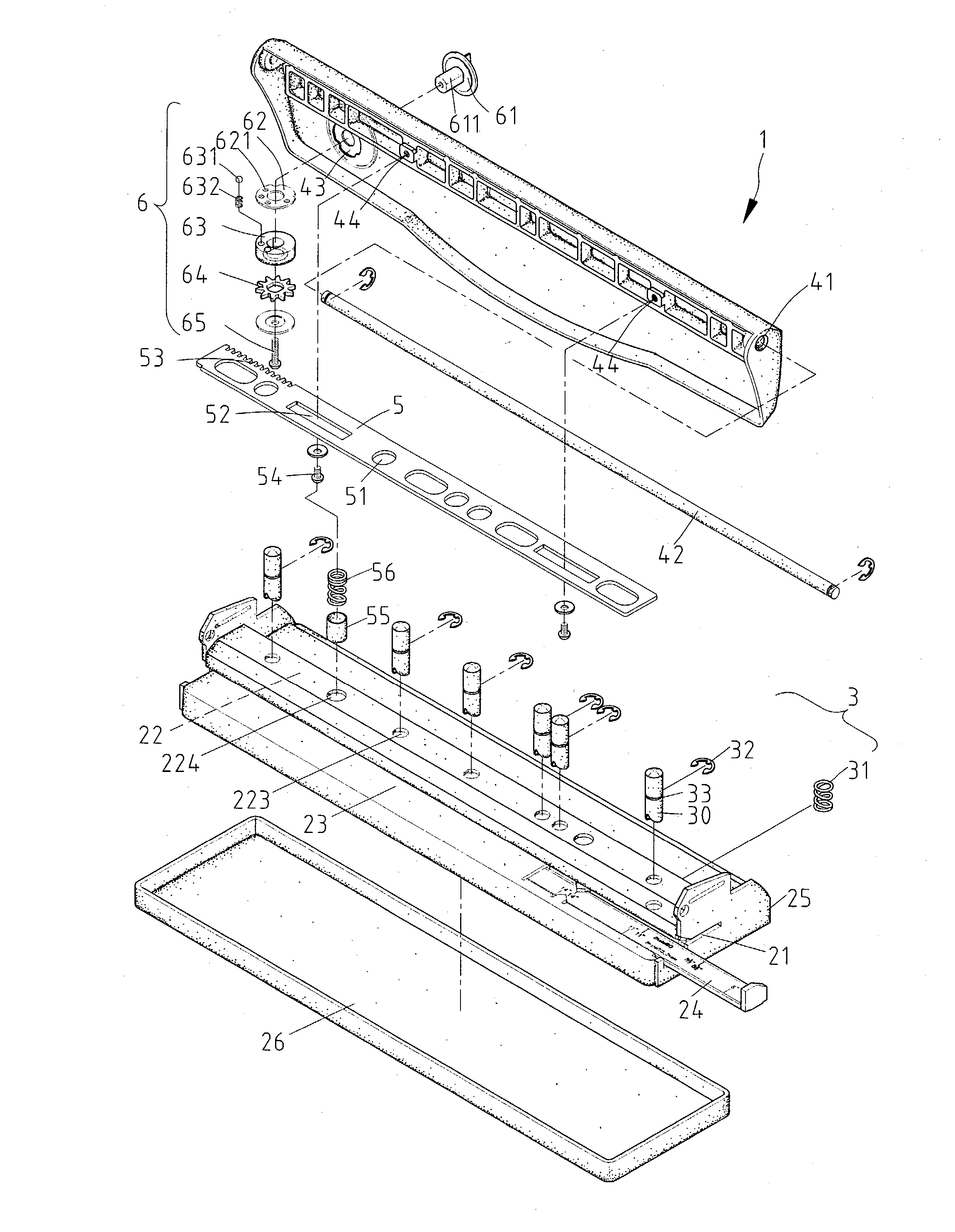
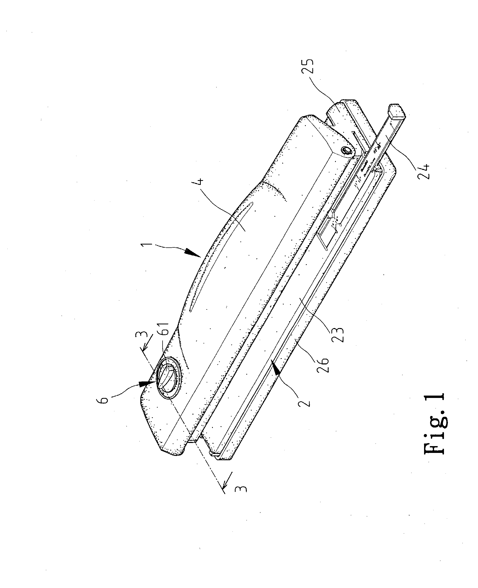
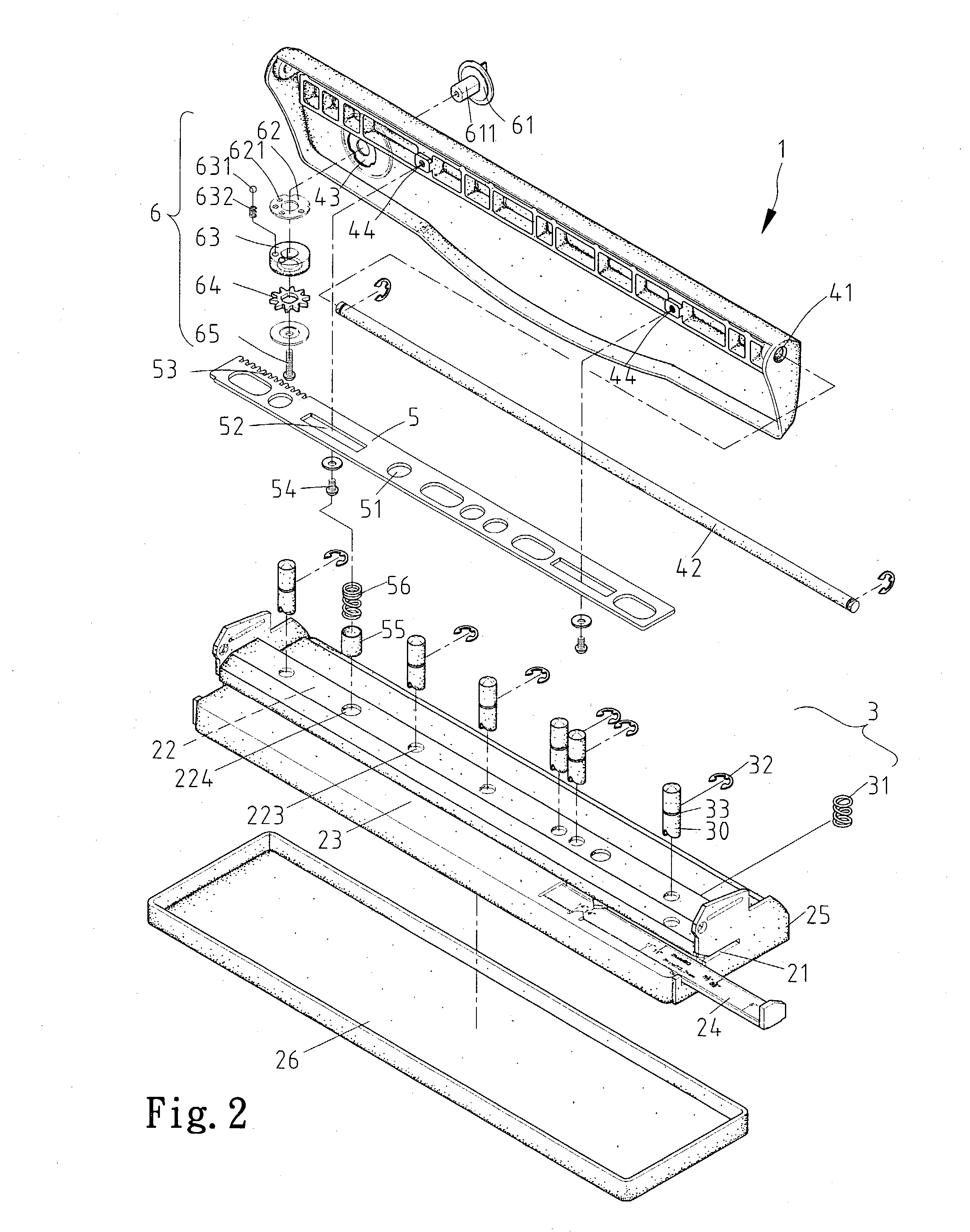
[0023] Referring to FIGS. 1.about.3, according to a first embodiment of the present invention, a punch 1 includes a base 2, a plurality of punch units 3, a plank 5 and a lever 4.

[0024] The base 2 includes a lower member 23 and an upper member 22 separated from the lower member 23 via a gap 21. The base 2 includes two lateral members 25 between which the lower member 23 and the upper member 24 are connected. The lower member 23 is put in a tray 26. The lower member 23 defines a plurality of holes (not numbered). A ruler 24 is movably mounted on the lower member 23. The upper member 22 defines a plurality of holes 223 and a hole 224. Each of the lateral members 25 defines a hole (not numbered).

[0025] Each of the punch units 3 includes a punch pin 30 for insertion through one of the holes 223 and one of the holes defined in the lower member 23, a spring 31 mounted on the punch pin 30 and a C-clip 32 received in an annular groove 33 defined in the punch pin 30.

[0026] The plank 5 include...


PUM

PropertyMeasurementUnit
distanceaaaaaaaaaa
distanceaaaaaaaaaa
rotationaaaaaaaaaa

Abstract

A punch includes a base, a plurality of punch pins, a lever and a plank. The base includes a lower member defining a plurality of holes and an upper member defining a plurality of holes corresponding to the holes defined in the lower member. Each of the punch pins is for insertion through one of the holes defined in the upper member and one of the holes defined in the lower member. The lever is pivotally mounted on the base. The plank defines a plurality of holes. The plank is movably attached to the lever between several positions in each of which it pushes a different set of the punch pins when the lever is operated.

Description

[0001] 1. Field of Invention[0002] The present invention relates to a punch with punch elements in adjustable positions.[0003] 2. Related Prior Art[0004] Taiwanese Patent Publication No. 241615 discloses a conventional punch including a base 3, a frame 2, a lever 1 and three punch units 4. The base 3 defines five holes 32. The frame 2 is mounted on the base 3. The frame 2 includes an upper portion and a lower portion. The lower portion of the frame 2 defines five holes 22 each communicated with one of the holes 32. The upper portion of the frame 2 defines five holes 22 each communicated with one of the holes 32. The punch units 4 are for insertion through three of the holes 22 and three of the holes 32. Each of the punch units 4 includes a sleeve 45, a spring 43 and a punch pin 41. The sleeve 45 includes a lower end fit in one of the holes 22 defined in the lower portion of the frame 2 and an upper end fit in one of the holes 22 defined in the upper portion of the frame 2. The sprin...

Claims


Application Information

Patent Timeline
Patent Type & Authority Applications(United States)
IPC IPC(8): B26F1/04B26F1/36
CPCB26F1/36B26F1/04Y10T83/8727Y10T83/885Y10T83/943Y10T83/944
Inventor LIN, CHIEN-FU
Owner CHAU LIH RONG ENTERPRISE
Why Eureka
Try Eureka