Bumper system with face-mounted energy absorber

a technology of energy absorption and bumper system, which is applied in the direction of bumpers, vehicle components, vehicular safety arrangements, etc., can solve the problems of inconsistent collapse of the bumper system, unfavorable vehicle safety, and unfavorable vehicle safety, so as to reduce damage to the vehicle, prevent the condition of die lock, and facilitate tooling

Inactive Publication Date: 2004-09-02
NETSHAPE INT LLC
View PDF12 Cites 25 Cited by
  • Summary
  • Abstract
  • Description
  • Claims
  • Application Information

AI Technical Summary

Benefits of technology

[0027] Bumper system 20 (FIG. 1) includes a bumper beam 21 attached to a vehicle, and an energy absorber 22 attached to a face of the bumper beam 21. The illustrated bumper beam 21 is attached by brackets 20A. Crush towers can also be used to mount the bumper beam. The illustrated beam is rollformed and swept (see Sturrus patent U.S. Pat. No. 5,454,504) and has a continuous B-shaped double-tubular cross section (FIG. 3). The double tubes are spaced vertically apart and include top and bottom mid-walls 23 and 24 defining a longitudinally-extending channel 25 along its front surface. A polymeric energy absorber 22 has a length with multiple top and bottom box-shaped sections 27 and 27' (not all being the same size or length) that abut the front surface 26 of the bumper beam 21. The energy absorber 22 further includes a plurality of rearwardly-extending nose sections 28 that extend into the channel 25. The nose sections 28 are trapezoidally-shaped to fit mateably into the channel 25, and extend about 50% to 60% of the way to a bottom of the channel 25. Where desired, the nose sections 28 include detents or are shaped to provide sufficient frictional engagement to temporarily retain the energy absorber 22 on the bumper beam 21. The illustrated nose sections 28 include collapse-controlling kick walls 30 and 31 that lie along and abut the top and bottom mid-walls 23 and 24 of the bumper beam 21. The kick walls 30 and 31 are non-parallel and are connected to the box-shaped sections 27 and 27' so that, upon impact by an object against the bumper system, the kick walls 30 and 31 bend in a predictable and preplanned manner and press into the top and bottom mid-walls 23 and 24. During high impact (see FIGS. 3 and 4), the kick walls 30 and 31 press with increasing force, resulting in a more consistent and controlled flexure and collapse of the box-shaped sections 27 of the polymeric energy absorber 22 and of the tube sections of the metal bumper beam 21 as a system. The nose sections 28 are trapped within the channel 25, which eliminates the problem of the energy absorber sliding vertically off a face of the bumper beam (which is a problem in some bumper systems using an energy absorber mounted to a face of a bumper beam).
[0049] Yet another important feature of the present illustrated design of the energy absorber 102 is shown by the offset 163A in lower wall 163, which connects the front and rear portions 163B and 163C of wall 163. During impact, the front portion 163B telescopes overlappingly onto the rear portion 163C, with the offset 163A wrapping back upon itself and between the portions 163B and 163C. This "wrapping" action provides high-energy absorption and a very consistent and predictable collapse, which is very desirable in energy absorbers.

Problems solved by technology

This is disadvantageous since mechanical fasteners require manual labor to install, which can add undesirably to cost.
Also, the mechanical fasteners can result in localized and non-uniform stress distribution during impact, resulting in inconsistent collapse of the bumper system and poor energy absorption on impact.
Further, fixing the energy absorber to the beams results in an inability of the energy absorber to shift and adjust to non-perpendicular and uneven loads transmitted from the impacting bodies.
At the same time, depending on the bumper system, sometimes shifting of an energy absorber is not good since it can result in unpredictable, premature and non-uniform collapse, resulting in poor or inconsistent energy absorption by the bumper system.
However, all of these alternatives have drawbacks.
For example, they each require a secondary operation, result in increased dimensional variation, and require significant investment in capital equipment.
Further, they can lead to increased scrap, a substantial increase in manpower and manufacturing time, and substantial increase in inventories and work in process.

Method used


Image

  • Bumper system with face-mounted energy absorber
  • Bumper system with face-mounted energy absorber
  • Bumper system with face-mounted energy absorber

Examples


Embodiment Construction

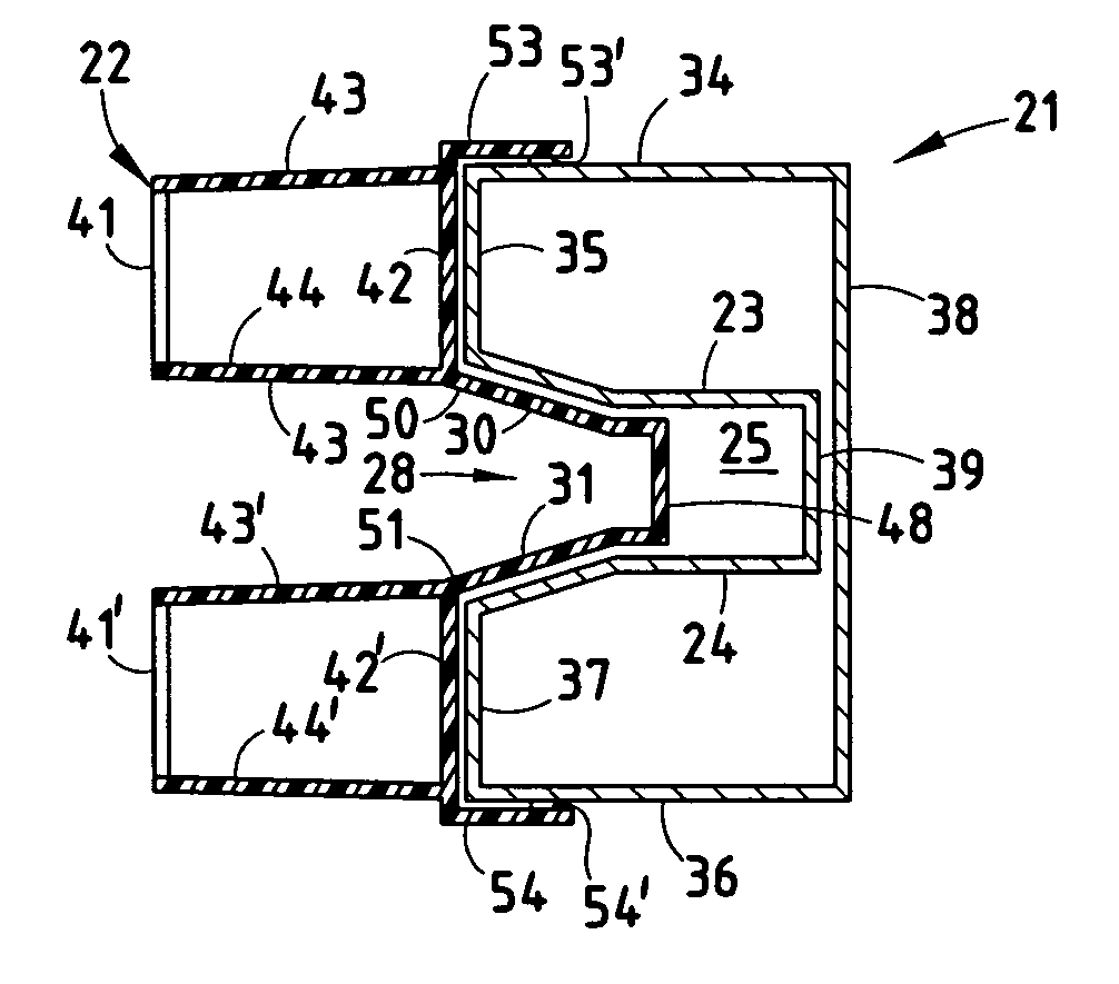
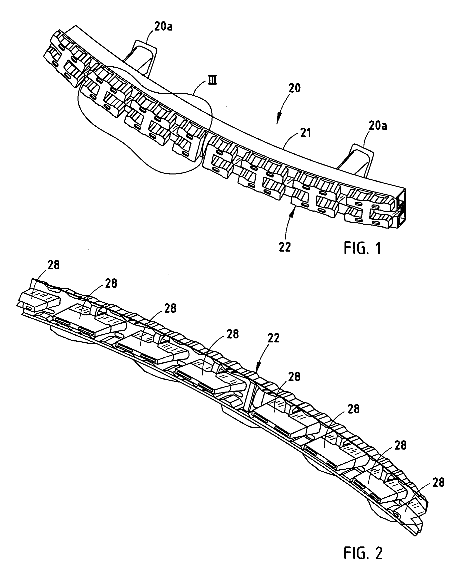
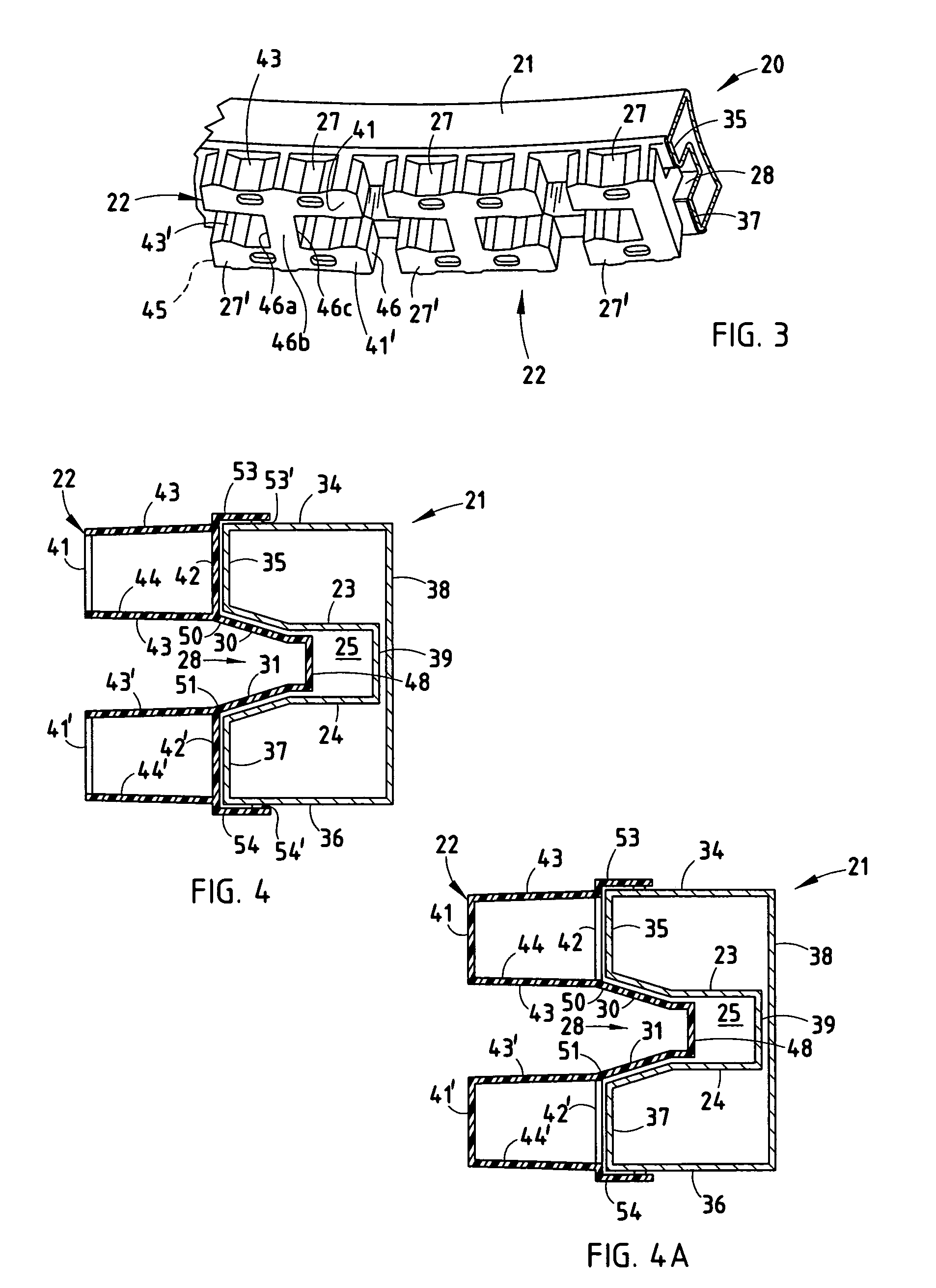
[0051] In regard to the illustrated preferred embodiment, a bumper system 320 (FIGS. 26-31) for vehicles includes a bumper beam 321 and an energy absorber 322 attached to a face of the bumper beam 321. The illustrated beam is rollformed and swept (see Sturrus patent U.S. Pat. No. 5,454,504) and has a continuous B-shaped double-tubular cross section (FIG. 27). The double tubes are spaced vertically apart and include top and bottom mid-walls 323 and 324 defining a longitudinally-extending channel 325 along its rear surface. A polymeric energy absorber 322 has a length with multiple box-shaped sections 327 (five box-shaped sections are shown, but not all are the same length) that abut the front surface 326 of the bumper beam 321. The energy absorber 322 further includes a plurality of tying sections 328 that extend longitudinally between the box-shaped sections 327 and also vertically between top and bottom portions 327 and 327" of the box-shaped sections 327, as discussed below.

[0052]...


PUM


Abstract

A bumper includes a beam and an energy absorber supported on its face. The beam includes front and rear beam walls, with a pair of apertures in the front beam wall, and further the energy absorber includes a pair of tubular structural columns extending from its front wall through the aperture in the front beam wall to the rear beam wall. By this arrangement, the front wall of the energy absorber receives support from the rear beam wall via the structural columns during a vehicle crash.

Description

[0001] This application is a divisional application of application Ser. No. 10 / 407,413, filed Apr. 4, 2003, entitled BUMPER SYSTEM WITH FACE-MOUNTED ENERGY ABSORBER, which is a continuation-in-part of application Ser. No. 10 / 061,670, filed Feb. 1, 2002, entitled BUMPER SYSTEM WITH FACE-MOUNTED ENERGY ABSORBER, which in turn claims benefit under 35 U.S.C. 119(e) of a provisional application Serial No. 60 / 283,969, filed Apr. 16, 2001, entitled BUMPER SYSTEM WITH FACE-MOUNTED ENERGY ABSORBER. This application is further a continuation-in-part of application Ser. No. 09 / 967,196, filed Sep. 28, 2001, entitled BUMPER SYSTEM WITH FACE-ABUTTING ENERGY ABSORBER, which in turn claims benefit of provisional application Serial No. 60 / 284,058, filed Apr. 16, 2001, entitled BUMPER SYSTEM WITH FACE-ABUTTING ENERGY ABSORBER under 35 USC .sctn.119.BACKGROUND OF THE PRESENT INVENTION[0002] The present invention relates to automotive bumper systems having beams and energy absorbers located-on faces of...

Claims


Application Information

Patent Timeline
Patent Type & Authority Applications(United States)
IPC IPC(8): B60R19/18
CPCB60R19/18B60R2019/1866B60R2019/1813
Inventor EVANS, DARINWEISSENBORN, MARK
Owner NETSHAPE INT LLC
Why Eureka
Try Eureka