Controlling of display parameter settings

a display parameter and control technology, applied in the field of controlling the display of image data, to achieve the effect of avoiding confusion at the user, effective and correct use of the depth range of the display devi

Inactive Publication Date: 2011-12-29
KONINKLIJKE PHILIPS ELECTRONICS NV
View PDF9 Cites 9 Cited by
  • Summary
  • Abstract
  • Description
  • Claims
  • Application Information

AI Technical Summary

Benefits of technology

It is an object of the invention to provide a more consistent control of the display parameters that are used at the display device.
The measures have the effect that the display parameters which are used for displaying the image data for the viewer are set as controlled by the display control mask structure. In particular the function of the second user control elements for setting the display parameters at the display device is masked according to the display control mask structure. Advantageously the display device now constitutes a controlled part of the rendering system with respect to setting the display parameters. The control is executed by transferring the display control mask structure from the source device to the display device, which advantageously allows the source device to implement any control function or restriction as indicated by the source of the image data, e.g. retrieved from a record carrier that contains both the image data and masking information.
In an embodiment of the rendering system the image data comprises depth information for displaying on a 3D display device, the second display parameters comprise display depth parameters, and the display control mask structure comprises depth masking control data for masking at least one depth parameter setting. The effect is that various elements are displayed at specific depth display positions under the control of the display control mask structure. Setting depth parameters has been considered previously to be just another display setting, which, in prior art devices, could be controlled by the user at the display device. However, the inventors have seen that some image data must be rendered under careful control of the depth parameter settings for avoiding confusion at the user, or even disturbing or nauseating effects due to distorted depth display rendering. Starting from such recognition the inventors provided a solution in that the display control mask structure is transferred with the image data to the display device to control the setting of depth parameters, while the control mask comprising the depth masking control data is generated at the source device. This has the advantage that the source device is enabled to control, limit and / or restrict the depth range at the display device in accordance with the image data to achieve an effective and correct use of the depth range of the display device.

Problems solved by technology

Hence the known system has the problem that the control of display parameters is provided at various points in the rendering system.

Method used


Image

  • Controlling of display parameter settings
  • Controlling of display parameter settings
  • Controlling of display parameter settings

Examples


Embodiment Construction

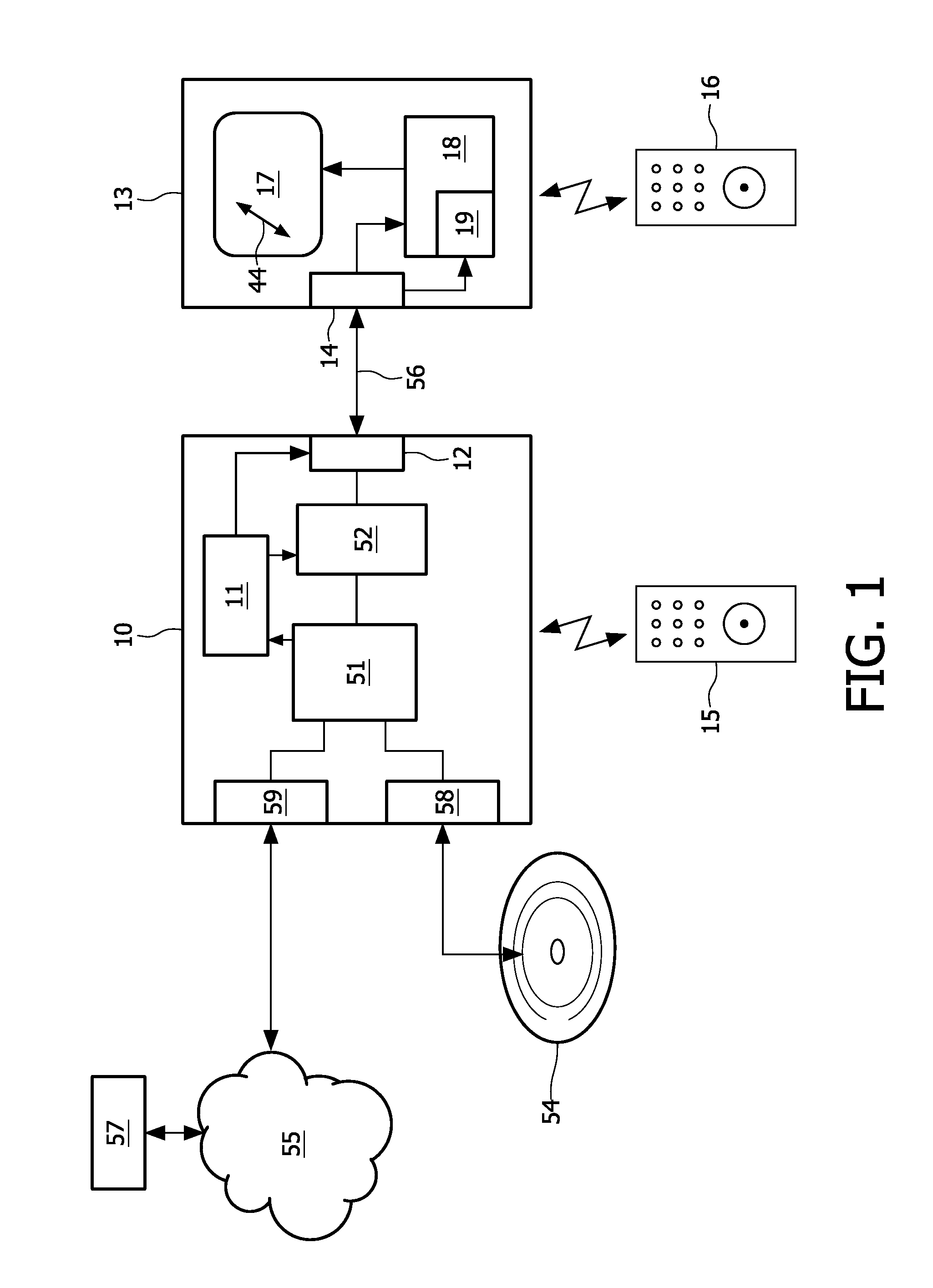
FIG. 1 shows a system for rendering image data, such as video, graphics or other visual information. A rendering device 10 is coupled as a source device to transfer data to a display device 13. The rendering device has an input unit 51 for receiving image information. For example the input unit device may include an optical disc unit 58 for retrieving various types of image information from an optical record carrier 54 like a DVD or BluRay disc. Alternatively, the input unit may include a network interface unit 59 for coupling to a network 55, for example the internet or a broadcast network. Image data may be retrieved from a remote media server 57.

The rendering device has a processing unit 52 coupled to the input unit 51 for processing the image information for generating transfer information 56 to be transferred via an output unit 12 to the display device. The processing unit 52 is arranged for generating the image data included in the transfer information 56 for display on the di...


PUM


Abstract

A system of controlling displaying of image data has a source device (10), for example a BD player, which processes source image data for outputting the image data in dependence of first display parameters, and has a user control (15) for controlling the display parameters. The image data is transferred from the source device to a display device (13), which displays the image data in dependence of further display parameters, and has a further user control (16) for setting the further display parameters. The source device provides a display control mask structure, which is transferred with the image data to the display device. The display device displays the image data in dependence of the display control mask structure by masking said setting of the further display parameters according to the display control mask structure. Advantageously in a 3D system the depth settings of the display device are controlled based on the display control mask structure based on data from the content author

Description

FIELD OF THE INVENTIONThe invention relates to a method of controlling displaying of image data, the method comprising at a source device, processing source image data for outputting the image data in dependence of first display parameters, the source device being provided with first user control elements for controlling the first display parameters, transferring the image data from the source device to a display device, and, at the display device, receiving the image data and displaying the image data in dependence of second display parameters, the display device being provided with second user control elements for setting the second display parameters.The invention further relates to a device for controlling displaying of image data, a display device for displaying image data, a signal and computer program product for controlling displaying of image data.The invention relates to the field of rendering and displaying image data, e.g. video, on a display device and controlling displ...

Claims


Application Information

Patent Timeline
Patent Type & Authority Applications(United States)
IPC IPC(8): G06T15/00G09G5/00H04N13/122
CPCH04N5/85H04N13/0497H04N13/0018H04N13/122H04N13/398H04N13/00G06T15/00
Inventor NEWTON, PHILIP S.SCALORI, FRANCESCODE HAAN, WIEBEVAN DER HEIJDEN, GERARDUS WILHELMUS THEODORUSBOLIO, DENNIS DANIEL ROBERT JOZEFVAN DOVEREN, HARRY F.P.
Owner KONINKLIJKE PHILIPS ELECTRONICS NV
Why Eureka
Try Eureka