Tool including bit and handle

a tool and handle technology, applied in the field of tools including bits and handles, can solve problems such as human casualties

Inactive Publication Date: 2004-09-09
LIOU MOU TANG
View PDF20 Cites 39 Cited by
  • Summary
  • Abstract
  • Description
  • Claims
  • Application Information

AI Technical Summary

Problems solved by technology

When this happens during operation, the bit 8 might cause human casualty.

Method used


Image

  • Tool including bit and handle
  • Tool including bit and handle
  • Tool including bit and handle

Examples


first embodiment

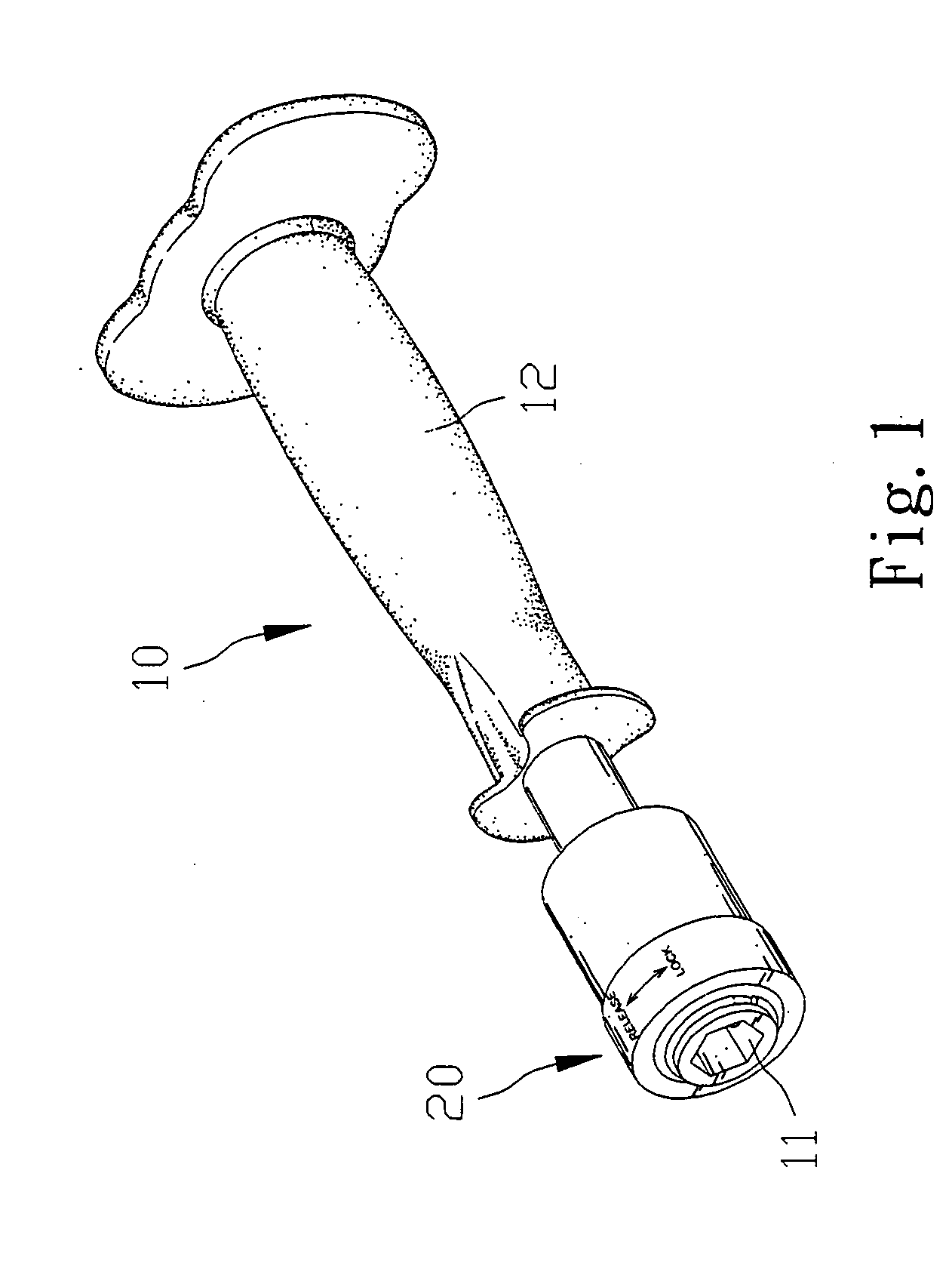
[0020] FIG. 1 shows a handle 10 according to the present invention. The handle 10 can be engaged with a bit 30 (FIG. 4) in a releasable manner to be described.

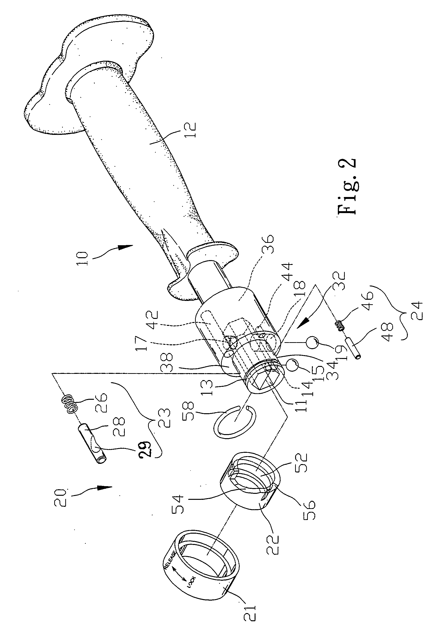
[0021] Referring to FIG. 2, the handle 10 includes a socket 32, a grip 12 extending from the socket 32 and a chuck 20 put around the socket 32.

[0022] The periphery of the socket 32 includes a thin section 34 and a thick section 36 so as to form an annular face 38 between the thin section 34 and the thick section 36. The socket 32 includes an annular groove 13 defined in the thin portion 34, an axial cavity 11 defined therein an end, a radial aperture 14 communicated with the axial cavity 11 in the thin section 34, a radial cavity 17 communicated with the axial cavity 11 in the thick section 36, a radial aperture 18 communicated with the axial cavity 11 opposite to the radial cavity 17, a longitudinal cavity 42 defined in the annular face 38 and communicated with the radial cavity 17 and a longitudinal cavity 44 defined in the ...

second embodiment

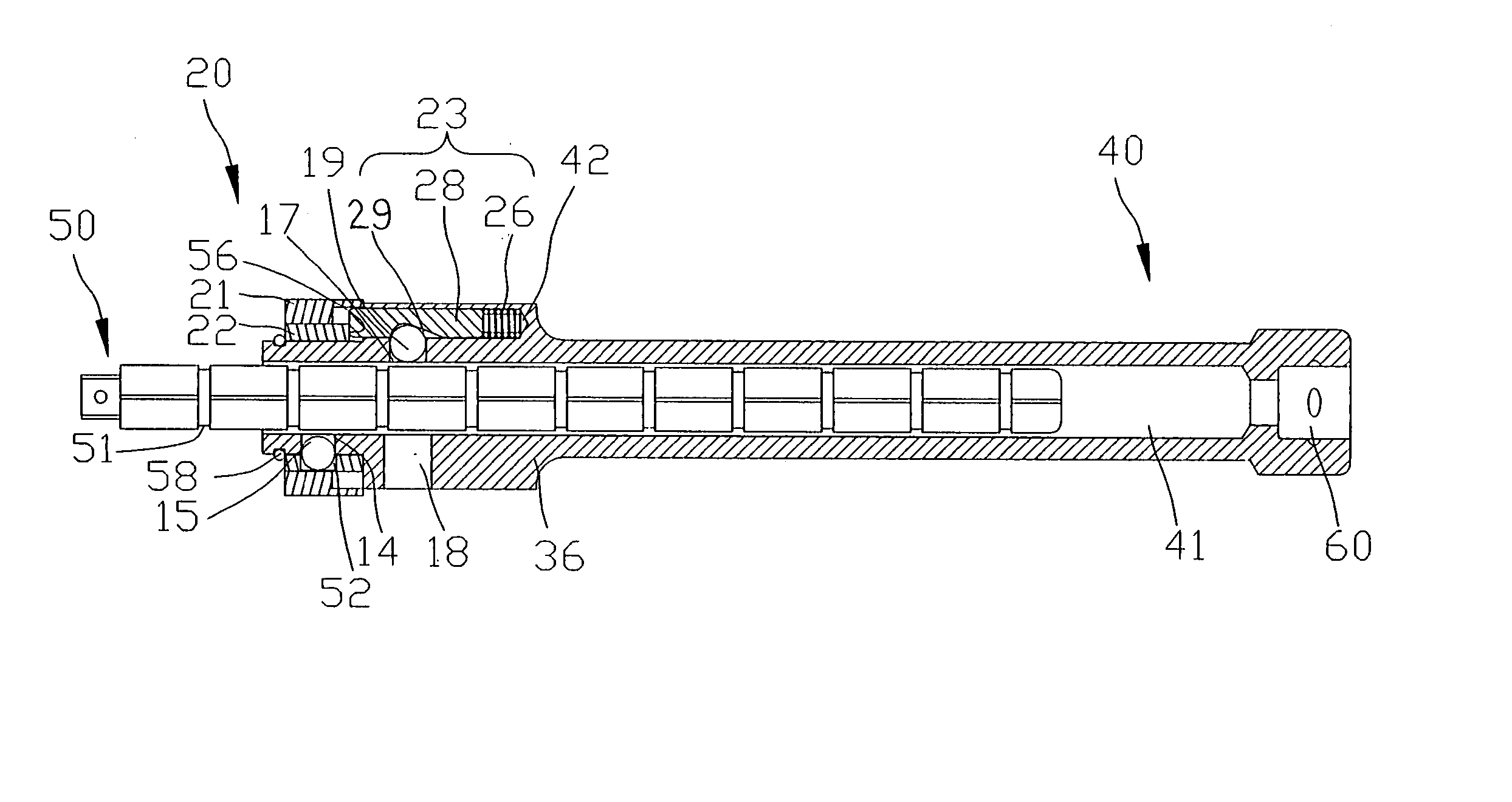
[0033] FIGS. 10 and 11 show a handle 40 according to the present invention. The handle 40 is identical to the handle 10 except for three things. Firstly, the handle 40 excludes the grip 12. Secondly, the handle 40 includes an axial cavity 41 longer than the axial cavity 11. Thus, the handle 40 can receive a long extensive shaft 50 instead of the bit 30. Finally, the handle 40 includes another axial cavity 60 opposite to the axial cavity 41. The axial cavity 60 enables the handle 40 to engage with a driving device (not shown).


PUM


Abstract

A handle is provided for use with a bit or extensive rod. The handle includes a socket. The socket includes a thin section, a thick section, an annular face between the thin and thick sections, an axial cavity and a radial aperture communicated with the axial cavity in the thin section. A detent is put in the radial aperture. A chuck is put on the socket for control over the detent.

Description

CROSS-REFERENCE[0001] The present application is a continuation-in-part application of U.S. patent application Ser. No. 10 / 271,274 filed on Oct. 16, 2002.[0002] The present invention relates to a tool including a bit and a handle for releasable engagement with the bit.BACKGROUND OF INVENTION[0003] In U.S. Pat. No. 5,934,384, a shaft 1, a stop 2, a C-clip 3, a spring 4, a ring 5, a chuck 6, a magnet 7 and a bit 8 are disclosed (FIG. 2). The shaft 1 includes a polygonal hole 10 in an end, an annular grove 11 in the periphery, an aperture 110 communicating the polygonal hole 10 with the annular groove 11, an annular groove 12 in the periphery and a polygonal rod 13 at an opposite end. The stop 2 includes a rod 20 extending from a central portion. The stop 2 is put in the annular groove 11 so that the rod 20 can be inserted into the polygonal hole 10 through the aperture 110. The C-clip 3 is put in the annular groove 12. The magnet 7 is fit in the polygonal hole 10. The chuck 6 includes...

Claims


Application Information

Patent Timeline
Patent Type & Authority Applications(United States)
IPC IPC(8): B25B23/00B25D3/00B25G3/26
CPCB25B23/0035B25D3/00B25G3/26B25D2250/105B25D2250/011
Inventor LIOU, MOU-TANG
Owner LIOU MOU TANG
Why Eureka
Try Eureka