Methods and systems for objective measurement of video quality

a video quality and objective measurement technology, applied in the field of methods and systems for objective measurement of video quality, can solve the problems of time-consuming and expensive, inability to achieve real-time results, and many limitations

Inactive Publication Date: 2004-09-09
LEE CHULHEE
View PDF4 Cites 27 Cited by
  • Summary
  • Abstract
  • Description
  • Claims
  • Application Information

AI Technical Summary

Problems solved by technology

Although the subjective test is considered to be the most accurate method since it reflects human perception, it has several limitations.
Thus, it is time-consuming and expensive.
Furthermore

Method used


Image

  • Methods and systems for objective measurement of video quality
  • Methods and systems for objective measurement of video quality
  • Methods and systems for objective measurement of video quality

Examples


embodiment 1

[0019] Embodiment 1

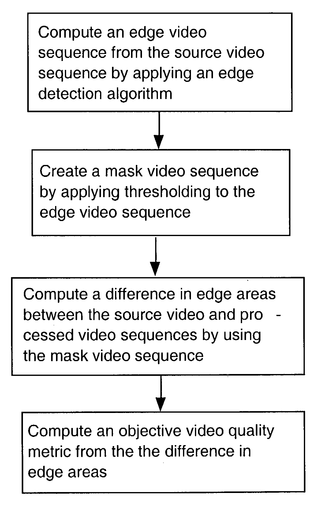
[0020] The present invention for objective video quality measurement is a full reference method. In other words, it is assumed that a reference video is provided. In general, a video can be understood as a sequence of frames or fields. Since the present invention can be used for field-based videos or frame-based videos, the terminology "image" will be used to indicate a field or frame. One of the simplest ways to measure the quality of a processed video sequence is to compute the mean squared error (MSE) between the source and processed video sequences as follows: 1 e mse = 1 LMN l m n ( U ( l , m , n ) - V ( l , m , n )) 2

[0021] where U represents the source video and V the processed video sequence. M is the number of pixels in a row, N is the number of pixels in a column, and L is the number of the frames. The PSNR is computed as follows: 2PSNR = 10log 10( P 2 e mse ) ( 3 )

[0022] where P is the peak pixel value. However, it has been reported that the PSNR (Peak ...

embodiment 2

[0037] Embodiment 2

[0038] Most color videos can be represented by using three components. A number of methods have been proposed to represent color videos, which include RGB, YUV and YC.sub.rC.sub.b [2]. The YUV format can be converted to the YC.sub.rC.sub.b format by scaling and offset operations. Y represents the grey level component. U and V (C.sub.r and C.sub.b) represent the color information. In case of color videos, the procedure described in Embodiment 1 may be applied to each component and the average may be used as an objective video quality metric. Alternatively, the procedure described in Embodiment 1 may be applied only to a dominant component, which provides the best performance, and the corresponding edge PSNR may be used as an objective video quality metric.

[0039] As another possibility, one may first compute the edge PSNR of a dominant component and use the other two edge PSNRs to slightly adjust the edge PSNR of the dominant component. For example, if the edge PSNR...

embodiment 3

[0043] Embodiment 3

[0044] FIG. 10 illustrates a system that measures video quality of a processed video. The system takes two input videos: a source video 100 and a processed video 101. If the input videos are analog signals, the system will digitize them, producing both source and processed video sequences. Then, the system computes an objective video quality metric using the methods described in the previous embodiments and output the objective video quality metric 102.


PUM


Abstract

New methods and systems for objective measurements of video quality based on degradation of edge areas are provided. By observing that the human visual system is sensitive to degradation around edges, objective video quality measurement methods that measure degradation around edges are provided. In the present invention, an edge detection algorithm is first applied to the source video sequence to find edge areas. Then, the degradation of those edge areas is measured by computing a difference between the source video sequence and a processed video sequence. From this mean squared error, the PSNR is computed and used as video quality metric.

Description

[0001] 1. Field of the Invention[0002] This invention relates to methods and systems for objective measurement of video quality.[0003] 2. Description of the Related Art[0004] Traditionally, the evaluation of video quality is performed by a number of evaluators who subjectively evaluate the quality of video. The evaluation can be done with or without reference videos. In referenced evaluation, evaluators are shown two videos: the reference (source) video and the processed video that is to be compared with the source video. By comparing the two videos, the evaluators give subjective scores to the videos. Therefore, it is often called a subjective test of video quality. Although the subjective test is considered to be the most accurate method since it reflects human perception, it has several limitations. First of all, it requires a number of evaluators. Thus, it is time-consuming and expensive. Furthermore, it cannot be done in real time. As a result, there has been a great interest i...

Claims


Application Information

Patent Timeline
IPC IPC(8): G06T7/00H04N5/14H04N17/00
CPCG06T7/0002G06T7/0085H04N17/00G06T2207/30168H04N5/142G06T2207/10016G06T7/13
Inventor LEE, CHULHEE
Owner LEE CHULHEE
Why Eureka
Try Eureka