Heat sink with preattached thermal interface material and method of making same

a technology of thermal interface material and heat sink, which is applied in the direction of electrical equipment, semiconductor devices, semiconductor/solid-state device details, etc., can solve the problem of tighter thermal budgets for thermal solution design

Inactive Publication Date: 2004-09-30
INTEL CORP
View PDF50 Cites 67 Cited by
  • Summary
  • Abstract
  • Description
  • Claims
  • Application Information

AI Technical Summary

Problems solved by technology

The increasing power consumption of processors results in tighter thermal budgets for a thermal solution design when the processor is employed in the field.

Method used


Image

  • Heat sink with preattached thermal interface material and method of making same
  • Heat sink with preattached thermal interface material and method of making same
  • Heat sink with preattached thermal interface material and method of making same

Examples


example 2

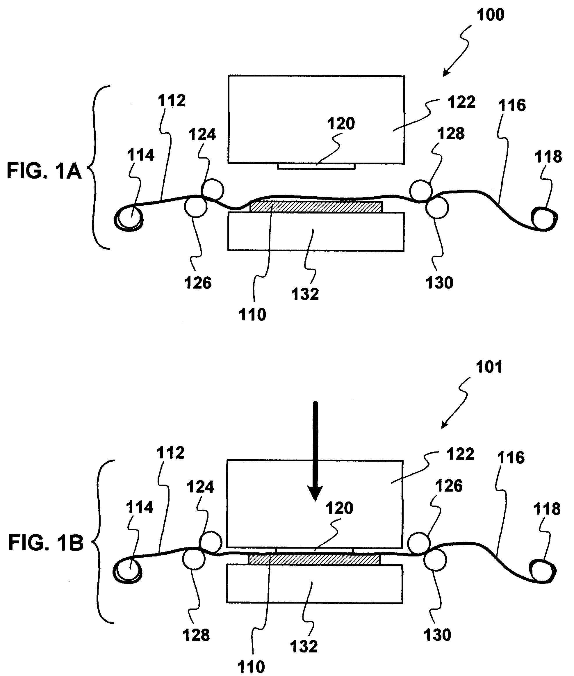
[0065] Reference is made to FIG. 1A, FIG. 1B, FIG. 3, and FIG. 8. In a second example, an IHS-grade copper heat spreader substrate 110 or 810 is stamped with an indium TIM 112. The indium TIM 112 is supplied to the press 122, and the press positive 120 is articulated in a stamping motion against the TIM 112. The TIM 112 is preheated by the support 132 to about 86.degree. C., and the press positive 120 exerts a force of about 400 pounds per square inch.

[0066] After the stamping process a heat sink assembly is achieved that includes a heat spreader substrate 310 (FIG. 3), and a TIM 313 with a rectangular profile 315. During the stamping process, a diffusion bonding zone 835 (FIG. 8) is formed between the heat spreader substrate 810 and the TIM layer 836. In this embodiment, the diffusion bonding zone 835 is an indium-copper IMC.

[0067] The shape of the TIM on the heat spreader substrate can vary according to a given application. In one embodiment, the shape of the TIM is substantially ...


PUM


Abstract

A process of making an integrated heat spreader is disclosed. The integrated heat spreader is stamped with a thermal interface material under conditions to form a diffusion bonding zone between the integrated heat spreader and the thermal interface material. The thermal interface material can have one of several cross-sectional profiles to facilitate reflow thereof against a die during a method of assembling a packaged microelectronic device. The thermal interface material can also have one of several footprints to further facilitate reflow thereof against the die.

Description

[0001] Disclosed embodiments relate to a thermal interface material for an integrated heat spreader. The thermal interface material is stamped from a rolled stock or flat sheet stock, directly onto an integrated heat spreader, or onto a heat sink in general such as an integrated heat spreader preform.BACKGROUND INFORMATIONDESCRIPTION OF RELATED ART[0002] An integrated circuit (IC) die is often fabricated into a microelectronic device such as a processor. The increasing power consumption of processors results in tighter thermal budgets for a thermal solution design when the processor is employed in the field. Accordingly, a thermal interface solution is often needed to allow the die to reject heat more efficiently.[0003] Various techniques have been employed to transfer heat away from a die. These techniques include passive and active configurations. One passive configuration involves a conductive material in thermal contact with the backside of a packaged die. This conductive materi...

Claims


Application Information

Patent Timeline
IPC IPC(8): H01L21/44H01L21/48H01L23/42
CPCH01L21/4882H01L23/42H01L2224/16H01L2224/73253H01L2924/01046H01L2924/01078H01L2924/01079H01L2924/01327H01L2924/16152H01L2924/00H01L2924/00014H01L2224/0401
Inventor HOULE, SABINA J.DEPPISCH, CARL
Owner INTEL CORP
Why Eureka
Try Eureka