
Sound pollution surveillance system and method

a sound pollution and surveillance system technology, applied in seismology, material analysis using acoustic emission techniques, acceleration measurement, etc., can solve the problems of logistically expensive and very inefficient, surveillance reports seldom cover full, and are not practical

Inactive Publication Date: 2004-10-07
SETI MEDIA
View PDF23 Cites 29 Cited by
  • Summary
  • Abstract
  • Description
  • Claims
  • Application Information

AI Technical Summary

Benefits of technology

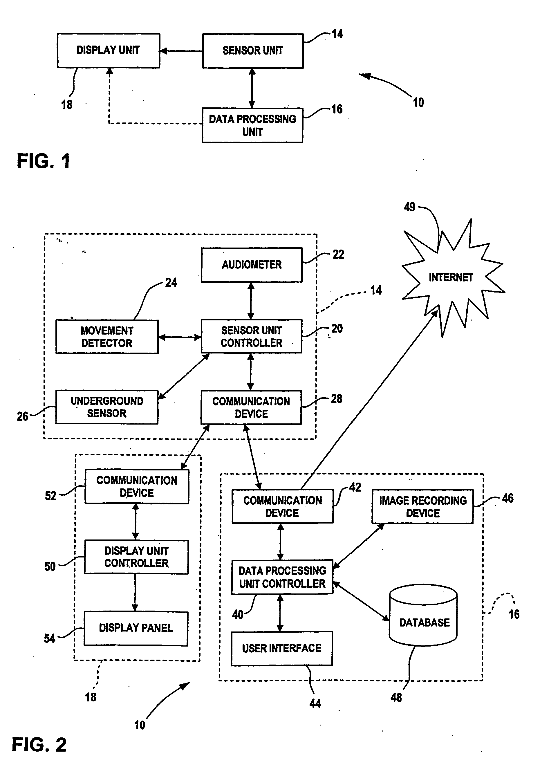
0012] FIG. 2 is a more detailed block diagram of the road sound pollution surveillance system in accordance with a preferred embodiment of the present invention;

Problems solved by technology

Although having a surveyor on site is a simple way of detecting sound infractions, this above-described practice is logistically expensive and very inefficient.
Surveillance reports seldom cover full days, unless surveyors are on site 24 hours a day, and this is not practical.
Roads often used by freight carriers such as trucks are the site of excessive noise levels.
For instance, compression braking, deficient maintenance on the trucks, heavy loads and speeding are various causes of excessive noise levels for freight carriers.
Excessive noise levels are problematic in some instances.
For example, a noisy truck traveling on a road in the vicinity of residential areas disturbs the local residents, especially in late-night or early-morning hours.
The method of having a surveyor on site is not logistically feasible for obvious reasons.

Method used


Image

  • Sound pollution surveillance system and method
  • Sound pollution surveillance system and method
  • Sound pollution surveillance system and method

Examples


Embodiment Construction

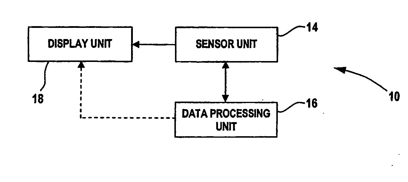
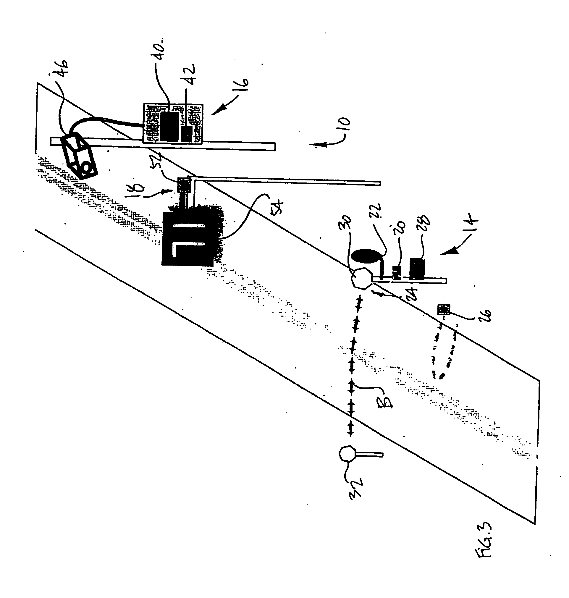
[0017] Referring to the drawings and, more particularly to FIG. 1, a road sound pollution surveillance system in accordance with the present invention is generally shown at 10, and will hereinafter be referred to as the RSP (road sound pollution) surveillance system 10. The RSP surveillance system 10 is generally composed of a sensor unit 14, a data processing unit 16 and a display unit 18. The sensor unit 14 comprises sensors that will measure various parameters in accordance with given uses of the RSP surveillance system 10. The sensor unit 14 is connected to the data processing unit 16 for the transmission of the information it detects and / or measures. Accordingly, relevant information is forwarded from the sensor unit 14 to the data processing unit 16. The data processing unit 16 will store the information and will be accessed by operators through a user interface thereof. The data processing unit 16 may also be a server connected to other computers by Ethernet or Internet to ha...


PUM

PropertyMeasurementUnit
heightaaaaaaaaaa
distanceaaaaaaaaaa
timeaaaaaaaaaa

Abstract

A system for detecting a sound level of vehicles comprising sensor units for detecting vehicles on a road and for measuring a sound level of a detected vehicle. A data processing unit is connected to the sensor units and has an identification recorder for operating the system by recording an identification of the vehicle detected if the sound level is above a given value.

Description

[0001] This application is a national entry of International Patent Application No. PCT / CA02 / 01228, filed on Aug. 7, 2002, and claims priority on Canadian Patent Application No. 2,357,060, filed on Aug. 10, 2001, and U.S. Provisional Patent Application No. 60 / 367,267, filed on Mar. 26, 2002.[0002] The present invention generally relates to surveillance of road sound pollution and, more particularly, to a system and a method for monitoring road sound levels to detect and identify infractions.[0003] It is a well known practice to monitor certain types of sound pollution by sending a surveyor on site equipped with a manual sound-level meter, audiometer, cameras or the like, to gather data relative to the sound environment at the site. Hence, a surveying report may be produced with the manually collected data, having information such as the type of sound emitted and its intensity, video imaging of the source of the sound emission, the date and hour of the sound emission, the geographic ...

Claims


Application Information

Patent Timeline
Patent Type & Authority Applications(United States)
IPC IPC(8): B60R11/02G01M17/007G01N29/00G01N29/14G01P1/12G01P3/36H04R29/00
CPCB60R11/02H04R29/00H04R29/001
Inventor NOEL, RENE
Owner SETI MEDIA
Learn More