Forced air warming unit

Inactive Publication Date: 2004-10-14
3M INNOVATIVE PROPERTIES CO +1
View PDF9 Cites 26 Cited by
  • Summary
  • Abstract
  • Description
  • Claims
  • Application Information

AI Technical Summary

Problems solved by technology

Some heat from this microenvironment is lost to the insulating layer; and some of this heat, in turn, is lost to surrounding room air.
The problem with any form of insulating covering is that it makes access to the patient more difficult for the physician.
While conduction is very efficient means to transfer heat, it is difficult to design a device that uniformly covers large areas of the body.
Uneven distribution of heat, if large enoug

Method used


Image

  • Forced air warming unit
  • Forced air warming unit
  • Forced air warming unit

Examples


Embodiment Construction

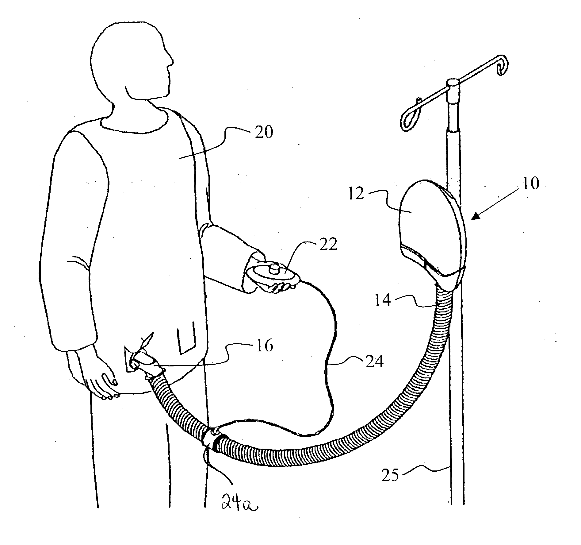
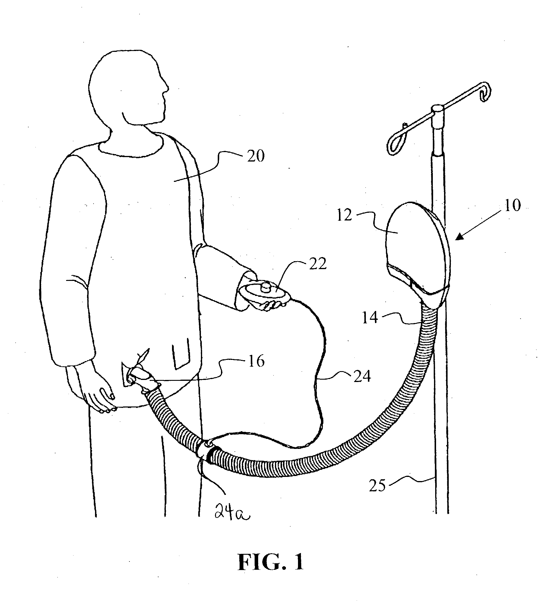
[0037] The invention concerns a forced air warming unit and more particularly, one with a manually-operated remote control available for use by a person in controlling thermal conditions of his or her own personal microenvironment to achieve and maintain a personalized state of thermal comfort in a clinical setting.

[0038] FIG. 1 illustrates the invention deployed for use in a clinical setting. In this regard, the invention extends to a forced air warming unit 10 for pressurizing and heating air in a casing 12. One end of an air hose 14 is connected to the casing 12, and the other end of the air hose is connected by a connector 16 to a pneumatic, convective device (not shown) which is disposed within a clinical garment 20 worn by a person in a clinical setting. In operation, the forced air warming unit 10 produces a stream of pressurized, heated air which exits the casing 12 into the one end of the air hose 14. The stream of pressurized, heated air is conducted by the air hose 14 to ...


PUM


Abstract

A forced air warming unit has a casing that encloses a scroll housing with a curved inside surface. A blower is disposed in the scroll housing inside the curved surface. Inlet and outlet openings are provided in the casing. A circuit board is mounted in the casing, against the scroll housing so that the blower is enclosed in space between the scroll housing and the circuit board. At least one opening is provided through the circuit board into the space in which the blower is disposed. A tapered, elongate, arcuate heater plate is disposed in the scroll housing between the circuit board and the blower, with a relatively wide end near the outlet opening and a second, relatively narrower end near the curved inside surface. Air is conducted in response to operation of the blower through the inlet opening, along a first side of the circuit board through the one or more openings in the circuit board into the scroll housing. Air is also conducted in response to operation of the blower along a second side of the circuit board which faces the scroll housing, through air passages in the circuit board to and along the first side through the one or more openings, into the scroll housing. Air entering the scroll housing in response to operation of the blower is accelerated by the blower along the curved inside surface while being heated in response to operation of the heater plate. Heated, pressurized air exits the forced air warming unit through the outlet opening. Provision is made for connecting an air hose to the outlet opening for conducting the pressurized, heated air to a pneumatic, convective device.

Description

[0001] This application contains subject matter related to that of U.S. patent application Ser. No. ______ and PCT Patent Application Serial No. ______, both for "PATIENT COMFORT APPARATUS AND SYSTEM", filed concurrently with this application, and to that of U.S. Design Patent Application Ser. No. ______, for "FORCED AIR WARMING UNIT".[0002] The present invention relates generally to thermal comfort. More particularly, the present invention relates to a portable warming apparatus for providing pressurized, thermally conditioned air to a pneumatic, convective device.[0003] The human body requires a controlled temperature for normal physiological processes to work properly. Because of this need, the body is endowed with a complex array of systems for regulating thermal homeostasis. The heat of metabolism is substantial and must be exhausted to the surrounding environment to prevent overheating. However if the heat loss is too great, hypothermia may result. For this and other reasons t...

Claims


Application Information

Patent Timeline
IPC IPC(8): A61F7/00A61F7/02
CPCA61B2017/00212A61F7/0085A61F7/0097A61F7/02A61F2007/0001A61F2007/006A61F2007/0094A61F2007/0234F04D29/582F04D29/626
Inventor HANSEN, GARY L.ZIAIMEHR, ALLEN HAMIDARNOLD, RANDALL C.
Owner 3M INNOVATIVE PROPERTIES CO
Why Eureka
Try Eureka